Operation
5.1 DM-F LOCAL
30
SIMOCODE pro - Fail-Safe Digital Modules
Manual, 11/2017, NEB631679702000/RS-AA/002
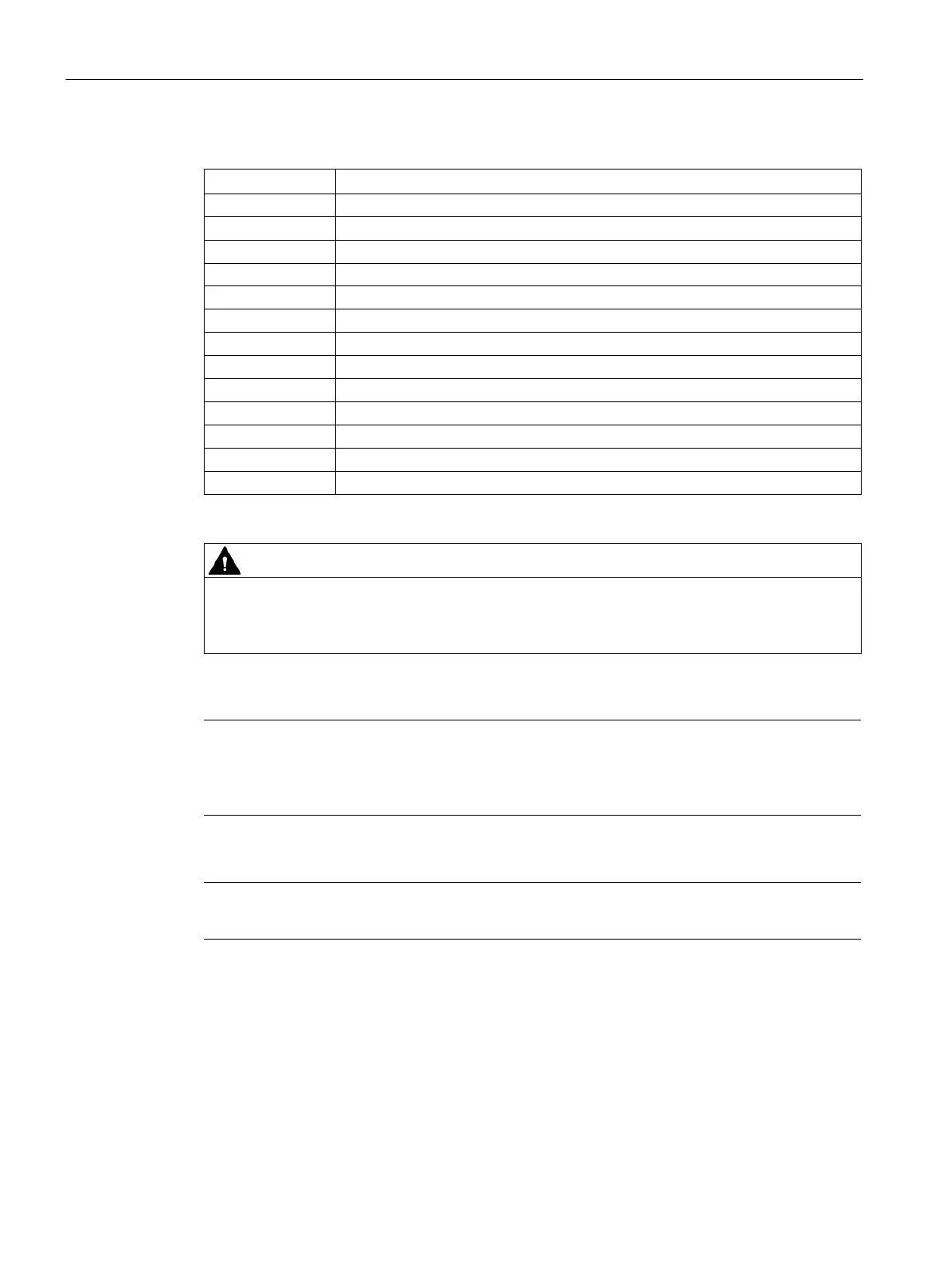
Table 5- 1 Terminal assignment of DM-F Local
Digital module, relay outputs 1 (60) and 2 (66)
61, 67 Relay enabling circuit 1, NO
Relay enabling circuit 2, NO
Y12, Y22 Sensor input channel 1, channel 2
Supply for sensor inputs (24 V DC, pulsed)
Start button (start after upwards and downwards edge)
Power supply connection 110 to 240 V AC/DC or +24 V DC
Ground (reference potential for sensor inputs; 3UF7320-1AU00-0 only)
Supply for sensor inputs (24 V DC, static)
1)
Loss of safety function possible.
For the 24 V DC power supply, always use a power supply according to IEC 60536
protection class III (SELV or PELV).
1)
pro via terminal SPE with the maximum possible cross-section and
s possible to the functional ground of the control cabinet, e.g. to the
grounded mounting plate of the control cabinet.
Note
Surge suppressors are required for inductive loads.