EasyManuals Logo

Siemens SIMOCODE pro Manual

Siemens SIMOCODE pro
118 pages
To Next Page IconTo Next Page
To Previous Page IconTo Previous Page
Page #64 background imageLoading...
Page #64 background image
Typical circuit diagrams
9.2 DM-F Local, sensor circuits
64
SIMOCODE pro - Fail-Safe Digital Modules
Manual, 11/2017, NEB631679702000/RS-AA/002
9.2.1
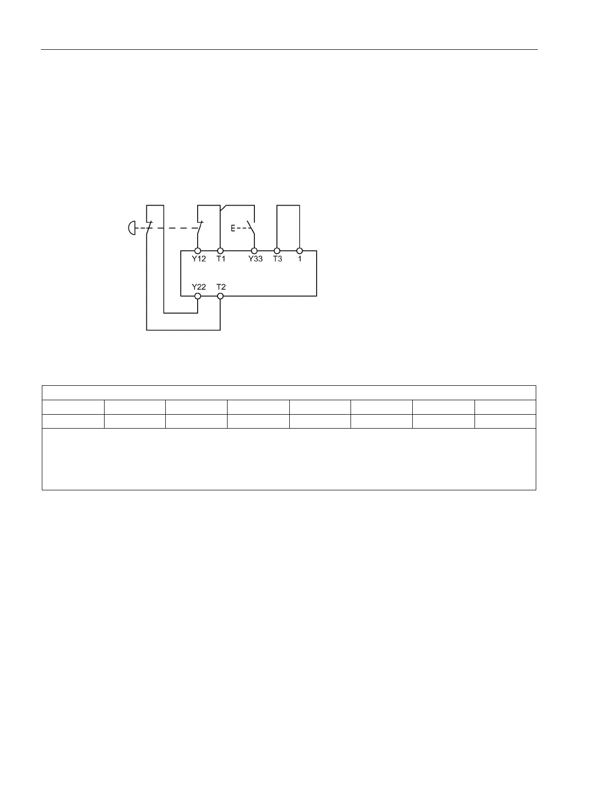
DM-F LOCAL, 2-channel, with cross-circuit detection and monitored start
3UF7320-1A.00-0
With cross-circuit detection
2 NC contacts
2-channel
Sensor input monitored start
Figure 9-3 Circuit diagram, 3UF7320-1A.00-0 with cross-circuit detection, 2 NC contacts, 2-channel,
monitored start
DIP switch
1 2 3 4 5 6 7 8
1
1
1
-
1
-
-
-
- : Switch position dependent on further requirements
Max. levels
Safety Integrity Level in accordance with IEC 61508/EN 62061 to SIL 3
Performance Level in accordance with EN ISO 13849-1 to PL e
DIP switch settings, 3UF7320-1A.00-0 with cross-circuit detection, 2 NC contacts, 2-channel, monitored start

Table of Contents

Other manuals for Siemens SIMOCODE pro

Questions and Answers:

Question and Answer IconNeed help?

Do you have a question about the Siemens SIMOCODE pro and is the answer not in the manual?

Siemens SIMOCODE pro Specifications

General IconGeneral
Protection ClassIP20
Mounting TypeDIN rail mounting
Rated Operational Voltage24 V DC
Rated CurrentUp to 820 A
Protection FunctionsOverload, short-circuit, phase failure, asymmetry, ground fault, motor stall
Operating Temperature Range-25°C to +60°C
Communication ProtocolsPROFIBUS DP, PROFINET, Modbus RTU
Analog OutputsUp to 2
Temperature MonitoringPTC/KTY, RTD (PT100/PT1000)
Digital OutputsRelay outputs, Solid-state outputs
Analog Inputs0/4-20mA, PT100/PT1000

Related product manuals