Typical circuit diagrams
9.3 DM-F LOCAL, actuator circuits
72
SIMOCODE pro - Fail-Safe Digital Modules
Manual, 11/2017, NEB631679702000/RS-AA/002
DM-F LOCAL, actuator circuits
Overview of DM-F Local, actuator circuit
This chapter contains examples showing the structure of the actuator circuit of the fail-safe
DM-F Local digital module for various safety requirements (with or without an incoming
supply contactor) and control functions (e.g. direct starter, reversing starter, star-delta
starter).
The examples illustrate the basic structure of the feedback circuit for monitoring the circuit
state of the contactors.
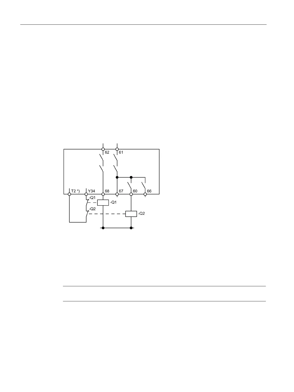
Actuator circuit with feedback circuit, control function = direct starter
Figure 9-11 Circuit diagram of an actuator circuit with feedback circuit, control function = direct
starter, with incoming supply contactor, maximum safety integrity level
SIL 3 / performance level PL e
*) Supply of feedback circuit from T3 for applications without cross-circuit detection
Q1: Incoming supply contactor
Q2: Motor contactor
Note
Protective circuit required to suppress surge voltages!