Planning/Configuring
6.2 Configuring the DM-F LOCAL
40
SIMOCODE pro - Fail-Safe Digital Modules
Manual, 11/2017, NEB631679702000/RS-AA/002
Configuring the DM-F LOCAL
-related functions can only be configured using the DIP switches.
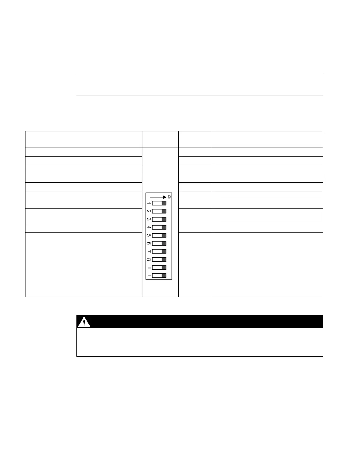
Table 6- 1 Factory setting
Without cross-circuit detection
With cross-circuit detection
Debouncing time for sensor inputs ∼ 50 ms
Debouncing time for sensor inputs ∼ 10 ms
Sensor input automatic start
Sensor input monitored start
Cascading input automatic start
Cascading input monitored start
Automatic starting after power failure (not
permissible in conjunction with start-up testing)
8 No automatic starting after power failure
No function - No function
Automatic starting after power failure. Risk of death or serious injury.
In the case of automatic starting after a power failure, the enabling circuits are connected
without pressing the Start button.
The desired configuration of the DM-F Local can be stored in SIMOCODE pro using the
SIMOCODE ES software (e.g. for documentation purposes). The stored configuration is then
compared with the actually effective settings on the DM-F Local (i.e., the settings defined
with the DIP switches). If the stored configuration is not the same as the effective
configuration, the following status message appears: "DM-FL Configuration deviates".