Operation
5.2 DM-F PROFIsafe
36
SIMOCODE pro - Fail-Safe Digital Modules
Manual, 11/2017, NEB631679702000/RS-AA/002
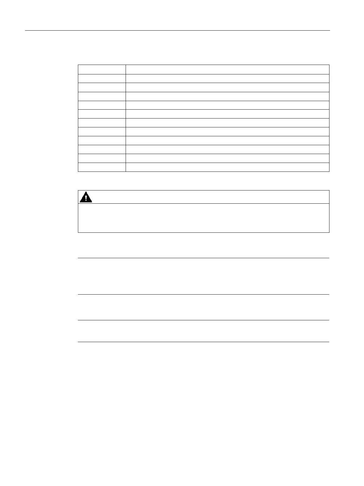
Table 5- 3 Terminal assignment of DM-F PROFIsafe
Digital module, relay outputs 1 (80) and 2 (86)
81, 87 Relay enabling circuit 1, NO
Relay enabling circuit 2, NO
83, 85, 89 Digital module, inputs 1, 2, 3
Supply for digital module, inputs 1 to 3, 24 V DC
Supply for feedback circuit 24 V DC
Power supply connection 110 to 240 V AC/DC or +24 V DC
Ground (reference potential for digital module inputs; 3UF7330-1AU00-0 only)
1)
Loss of safety function possible.
For the 24 V DC power supply, always use a power supply according to IEC 60536
protection class III (SELV or PELV).
1)
pro via terminal SPE with the maximum possible cross-section and
with as short a cable as possible to the functional ground of the control cabinet, e.g. to the
grounded mou
nting plate of the control cabinet.
Note
Surge suppressors are required for inductive loads.