EasyManuals Logo

Siemens SIMOCODE pro Manual

Siemens SIMOCODE pro
118 pages
To Next Page IconTo Next Page
To Previous Page IconTo Previous Page
Page #62 background imageLoading...
Page #62 background image
Typical circuit diagrams
9.1 Introduction
62
SIMOCODE pro - Fail-Safe Digital Modules
Manual, 11/2017, NEB631679702000/RS-AA/002
(1)
Actuator circuit
Local operation
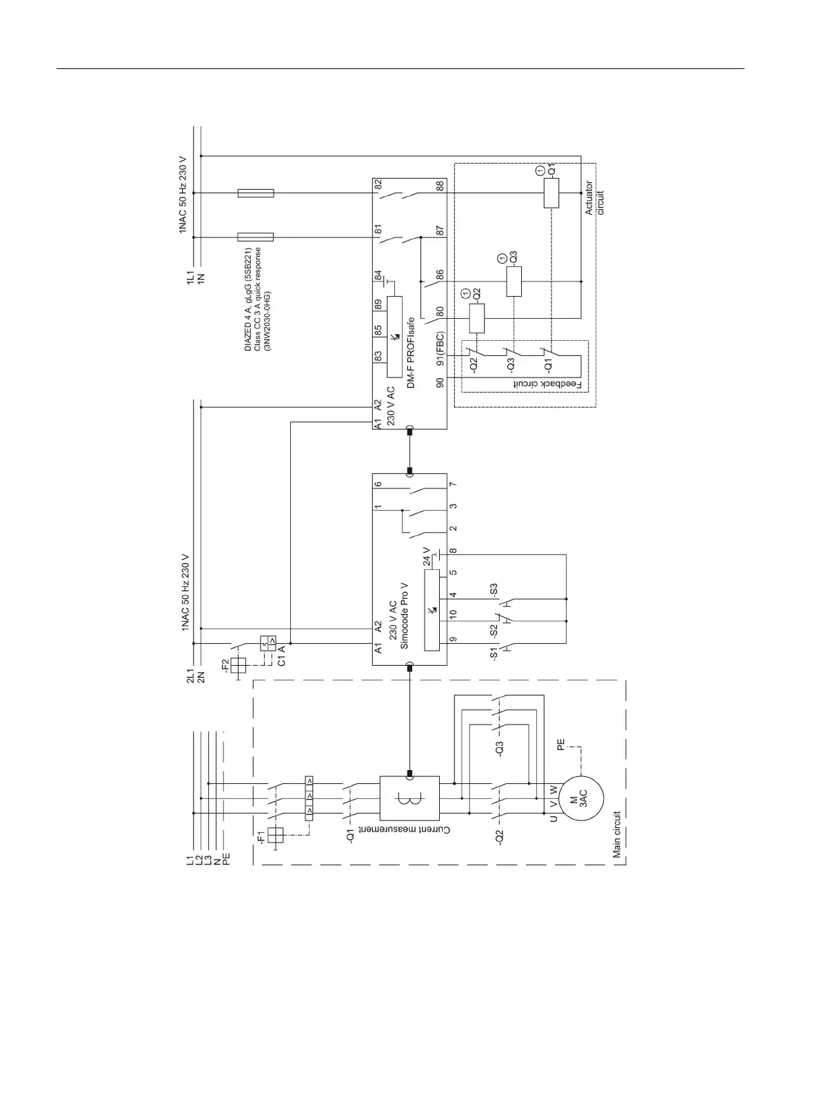
Protective circuit required to
suppress surge voltages!
Q1 = Incoming supply contactor
S1 = CW rotation
Q2 = Motor contactor CW
S2 = Off
Q3 = Motor contactor CCW
S3 = CCW rotation
Figure 9-2 Typical circuit diagram of a reversing starter with safety-related tripping via
PROFIBUS / PROFIsafe or PROFINET / PROFIsafe, maximum level SIL 3 or PL e

Table of Contents

Other manuals for Siemens SIMOCODE pro

Questions and Answers:

Question and Answer IconNeed help?

Do you have a question about the Siemens SIMOCODE pro and is the answer not in the manual?

Siemens SIMOCODE pro Specifications

General IconGeneral
Protection ClassIP20
Mounting TypeDIN rail mounting
Rated Operational Voltage24 V DC
Rated CurrentUp to 820 A
Protection FunctionsOverload, short-circuit, phase failure, asymmetry, ground fault, motor stall
Operating Temperature Range-25°C to +60°C
Communication ProtocolsPROFIBUS DP, PROFINET, Modbus RTU
Analog OutputsUp to 2
Temperature MonitoringPTC/KTY, RTD (PT100/PT1000)
Digital OutputsRelay outputs, Solid-state outputs
Analog Inputs0/4-20mA, PT100/PT1000

Related product manuals