Typical circuit diagrams
9.3 DM-F LOCAL, actuator circuits
SIMOCODE pro - Fail-Safe Digital Modules
Manual, 11/2017, NEB631679702000/RS-AA/002
81
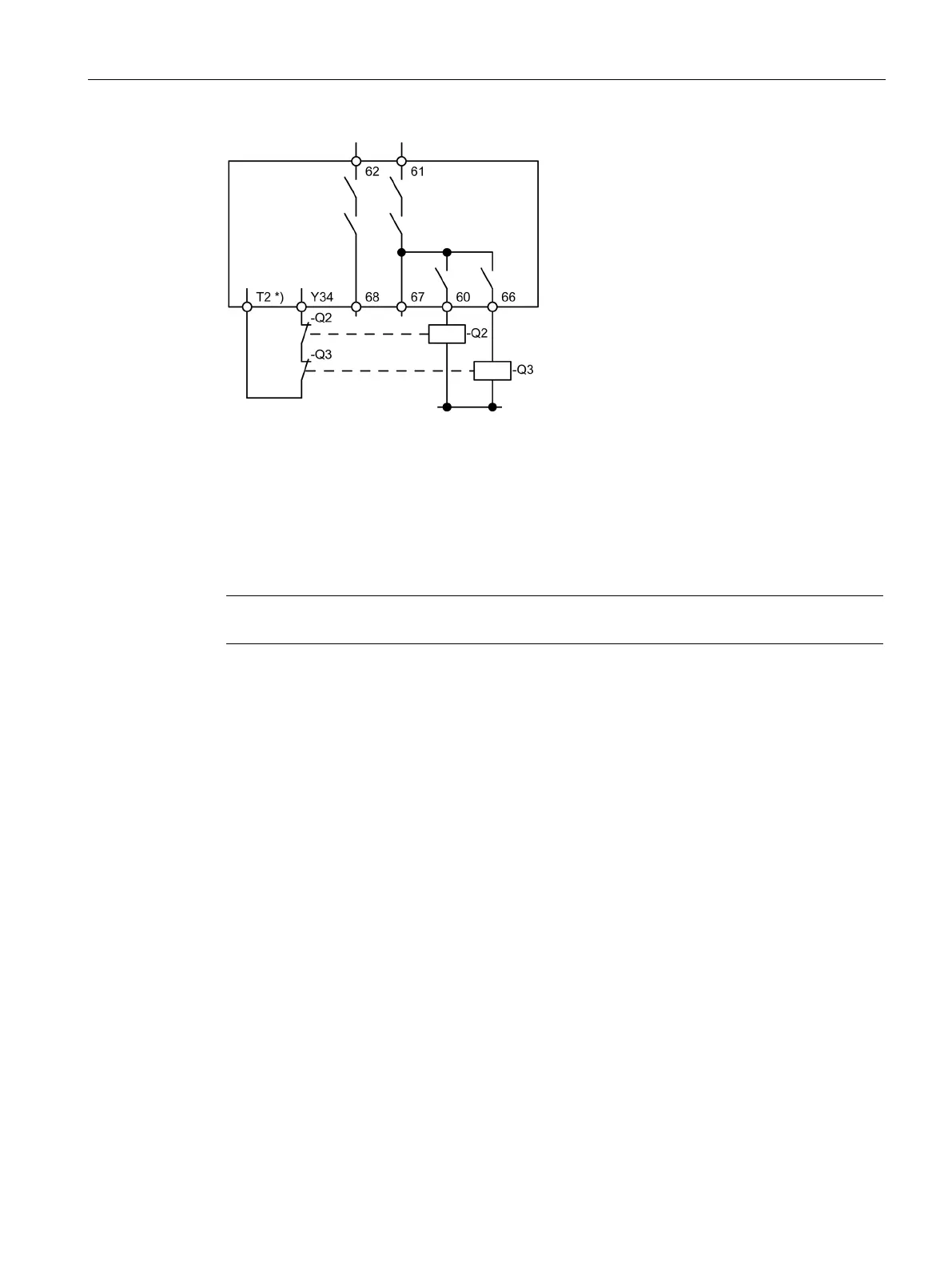
Figure 9-20 Circuit diagram of an actuator circuit with feedback circuit, control function = pole-
changing starter, without incoming supply contactor, maximum safety integrity level
SIL 1 / performance level PL c
*) Supply of feedback circuit from T3 for applications without cross-circuit detection
Q2: Line contactor, fast
Q3: Line contactor, slow
Note
Protective circuit required to suppress surge voltages!