Assembly
5.2 Installing the machine
Standard motors SH 63 ... 355
52 Operating Instructions, 12/2018, A5E38483075A
5.2.4.1 Mounting and withdrawing output transmission elements
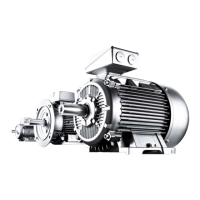
Withdrawing output transmission elements
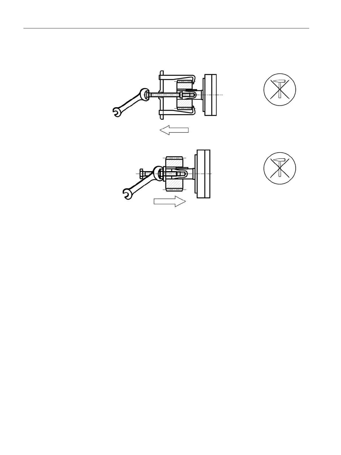
Mounting output transmission elements
● When mounting output transmission elements (coupling, gear wheel, belt pulley etc. ) use
the thread at the shaft end.
If possible, heat up the output transmission elements as required.
● Use a suitable device when withdrawing output elements.
● When mounting or withdrawing, do not apply any blows, for example with a hammer or
similar tool, to the parts to be mounted or withdrawn.
● Only transfer radial or axial forces specified in the catalog to the motor bearings via the
shaft extension.
5.2.5 Machines with type of construction IM B15, IM B9, IM V8 and IM V9
Types of construction without bearings on the drive side
These machines do not have their own bearing system for the machine shaft at the drive end
(DE). The machine shaft is accepted by the (hollow) shaft or coupling of the system or driven
machine.
● Using the centering edge, the machine is aligned with respect to enclosures, flanges or
driven machines.
● Note that the temperature of the motor and motor shaft increases during operation. The
thermal expansion of the machine shaft must be compensated by the customer by