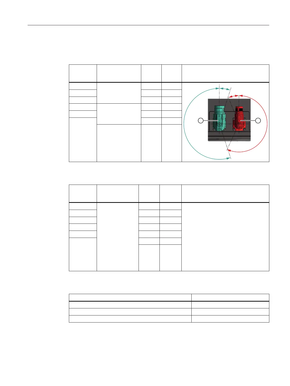
Rotatability of the power connector and signal connector
Table 8-3 Rotation range of the power connector ①
Motor Connector size of
the power connec‐
tor ①
Angle α Angle α' Drawing
1F☐2☐03 M17 205 29
1F☐2☐04 205 25
1F☐2☐05 228 35
1F☐2☐06 M23 222 40
1F☐2☐08 222 46
1F☐2☐10
222 55
M40 228 48
Table 8-4 Rotation range of the signal connector ②
Motor Connector size of
the signal connec‐
tor ②
Angle β Angle β' Drawing
1F☐2☐03
M17
209 25 See table "Rotation range of the power con‐
nector"
1F☐2☐04 205 25
1F☐2☐05 215 48
1F☐2☐06 215 41
1F☐2☐08 215 46
1F☐2☐10 215 57
210 48
Table 8-5 Maximum rotating torque for the connectors
Connectors Max. torque when rotating
Connector M17 8 Nm
Connector M23 12 Nm
Connector M40 20 Nm
Electrical connection
8.3 System integration
1FK2 Synchronous Motors for SINAMICS S120
Conguration Manual, 02/2022, A5E46927724B AD 139
 Loading...


