4.2.3 Technical specications
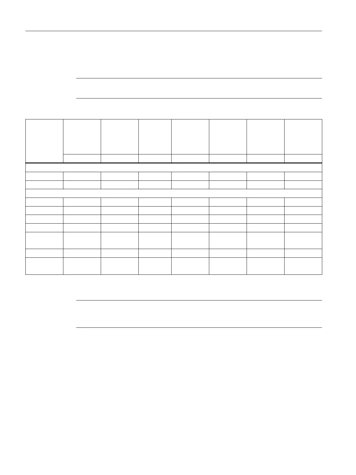
The following table contains technical specications of the holding brakes:
Note
The following specications apply to control with 24 V DC.
Motor type Holding tor‐
que
at 120 °C
Dyn. braking
torque
Rated cur‐
rent
Opening
time
1)
Closing
time
1)
Maximum
permissible
single oper‐
ating
energy
2)
Total operat‐
ing energy
(service life)
M
4
/ Nm M
1m
/ Nm I
supp
/ A t / ms t / ms W
max
/ J W
total
/ kJ
For spring-loaded brake
1F☐2☐03 1.3 1.3 0.4 90 30 62 5
1F☐2☐04 3.3 3.3 0.5 110 40 270 35
For permanent-magnet brake
1F☐2☐05 8 5 0.6 90 25 568 284
1F☐2106 16 9 0.7 100 50 1065 774
1F☐2206 13 6.5 0.7 100 50 1548 774
1F☐2☐08-3 19 12 0.8 100 40 2000 1800
1F☐2☐08-4
1F☐2☐08-5
32 17 0.9 200 60 4800 2400
1F☐2☐10-3 32 17 0.9 200 60 6658 2400
1F☐2☐10-4
1F☐2☐10-5
55 26 1.0 220 80 8700 3800
1)
Measured with varistor for a rated holding brake voltage of 24 V DC.
2)
Maximum three EMERGENCY STOP operations in sequence with a maximum of 25% total operating energy
Note
If the brake is switched in two stages (two clicks), the rst switching point is decisive for opening
and the second for closing.
Motor components
4.2 Holding brake
1FK2 Synchronous Motors for SINAMICS S120
62 Conguration Manual, 02/2022, A5E46927724B AD