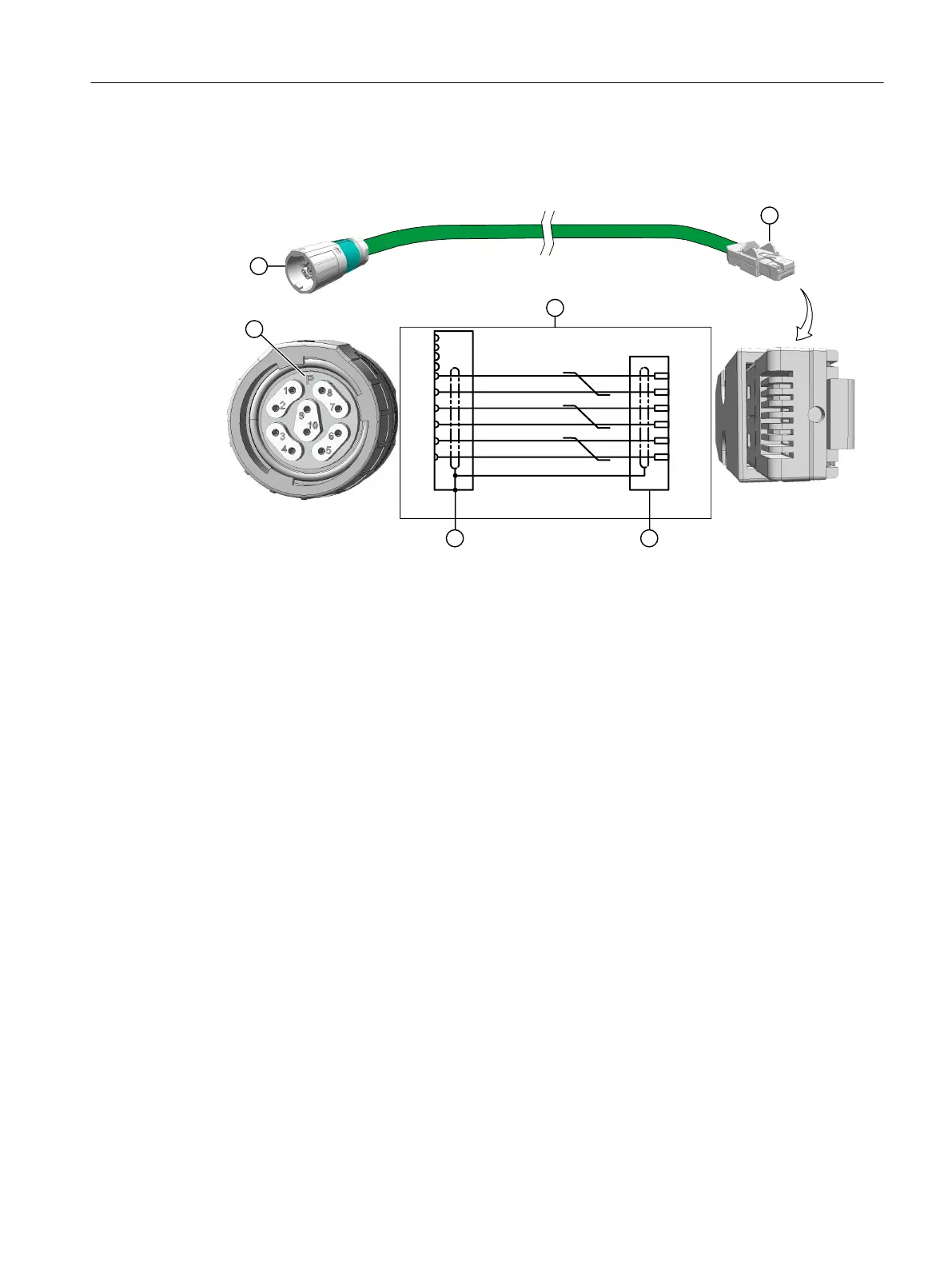
Connection diagram of the signal line for the 1F☐2 motor on the S120
The connection is made on a signal line with connector M17, 10-pin and RJ45 connector
#
"
1
591
59/
391
39/
7
77
#,
3%
391
39/
591
59/
7
"
#
#6
1,
:&
(/
p
1 M17 round connector, 10-pin 4 Pin assignment of M17 round
connector, 10-pin
2 RJ45/IP20 connector 5 Pin assignment of the RJ45 con‐
nector
3 Connection diagram P 0° coded
Locking the round connector
Lock the round connector properly on the motor
Information on locking is provided in Chapter "Handling the quick-action locking (Page 146)".
Electrical connection
8.3 System integration
1FK2 Synchronous Motors for SINAMICS S120
Conguration Manual, 02/2022, A5E46927724B AD 145
 Loading...


