For connector size M40
7
8
6
8-%-
7-
6-$-
7-
#%
(/:&
8)
#,
#,
#,
#,
#%
8-%-
1&
#3
8
7
6
8
7
6
6-$-
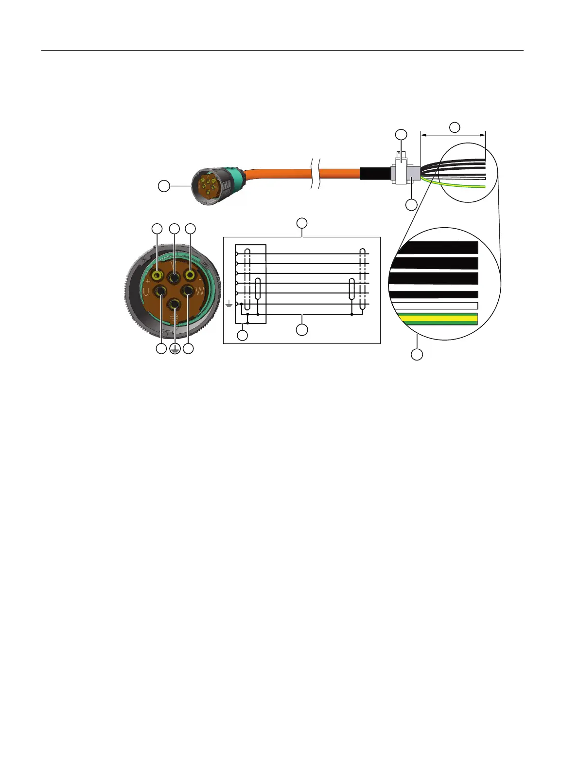
1 MOTION-CONNECT cable with SPEED CONNECT plug, size M40
2 Terminal for the cable shield
3 Cable shield
4 Connection diagram
U; V; W = power cables, 1.5 mm
2
, each cable with separate shielding
BD1+ and BD2- = brake cable without lettering, 1.5 mm
2
, shielded together
PE = protective conductor
5 Cable shield
6 Conductor designations
7 Recommended length of the cable ends: 105 mm
Locking the round connectors
Properly lock the connected round connector at the motor.
Information on locking is provided in Chapter "Handling the quick-action locking (Page 146)".
Electrical connection
8.3 System integration
1FK2 Synchronous Motors for SINAMICS S120
144 Conguration Manual, 02/2022, A5E46927724B AD
 Loading...


