The Control Unit uses the following Modbus function codes:
● FC 03: Holding register to read data from the inverter
● FC 06: Write single register to write to individual register
● FC 16: Write to multiple registers to write to several registers
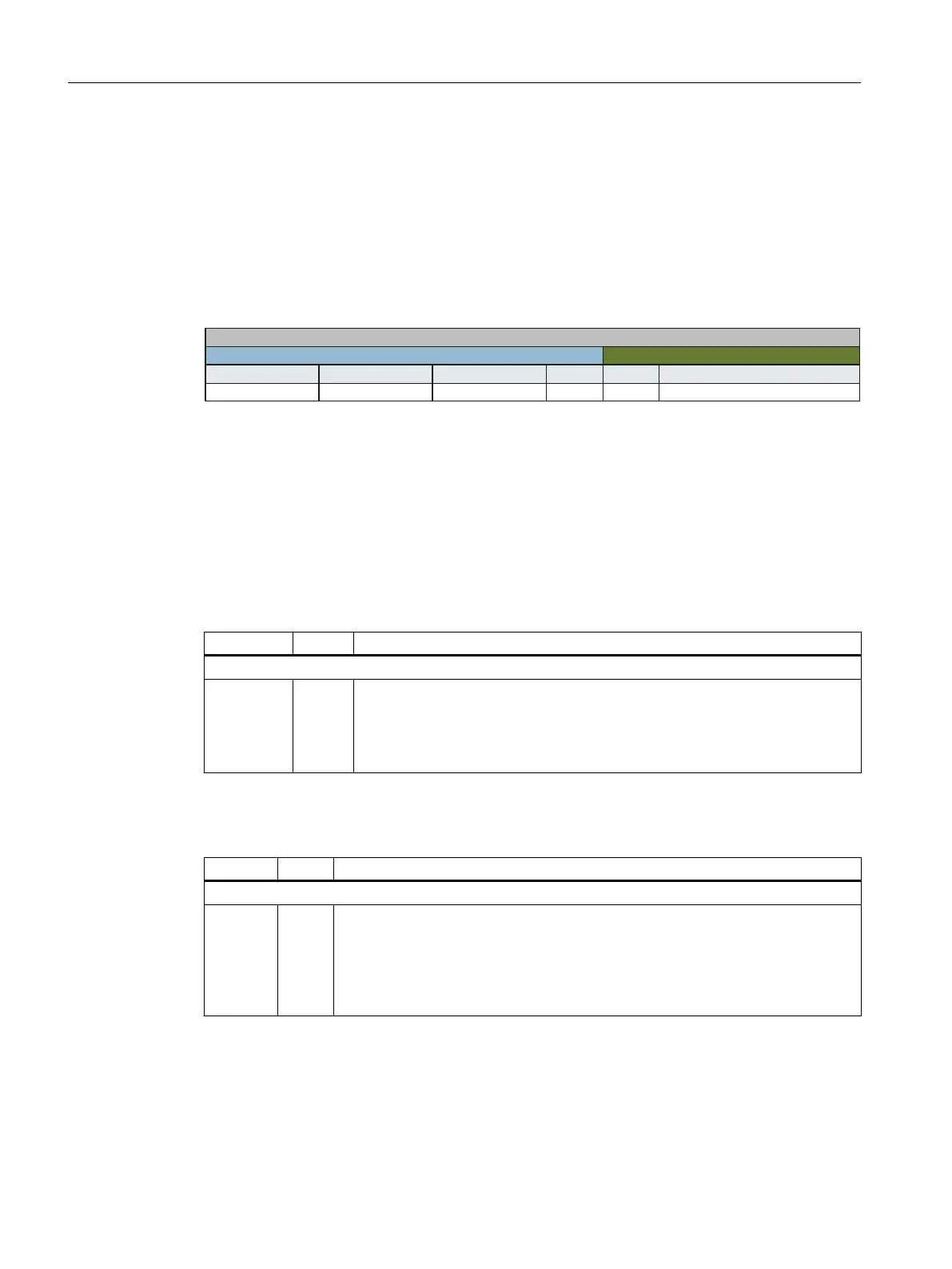
Structure of a Modbus TCP message
Transaction ID Protocol ID
Length
Unit ID
FCode
1 Byte1 Byte2 Bytes2 Bytes2 Bytes
0 ... 252 Bytes
Protocol Data Unit (PDU)
Modbus Application Header
Application Data Unit (ADU)
Data
Figure A-38 Individual components, including Modbus Application Header (MBAP) and function code
Structure of a read request via Modbus function code 03 (FC 03)
Any valid register address is permitted as the start address.
Via FC 03, the control can address more than one register with one request. The number of
addressed registers is contained in bytes 10 and 11 of the read request.
Table A-17 Structure of a read request for device number 17, example
Value Byte Description
MBAP header
03 h
00 h
6D h
00 h
02 h
7
8
9
10
11
Register start address "High" (register 40110)
Register start address "Low"
Number of registers "High" (2 registers: 40110; 40111)
number of registers "Low"
The response returns the corresponding data set:
Table A-18 Device response to the read request, example
Value Byte Description
MBAP header
03 h
04 h
11 h
22 h
33 h
44 h
7
8
9
10
11
12
Number of bytes (4 bytes are returned)
Data first register "High"
Data first register "Low"
Data second register "High"
Data second register "Low"
Communication
A.1 Communication
Industrial Security
182 Configuration Manual, 08/2017, A5E36912609A