Start-Up
2-24 SINUMERIK 801
Start-Up
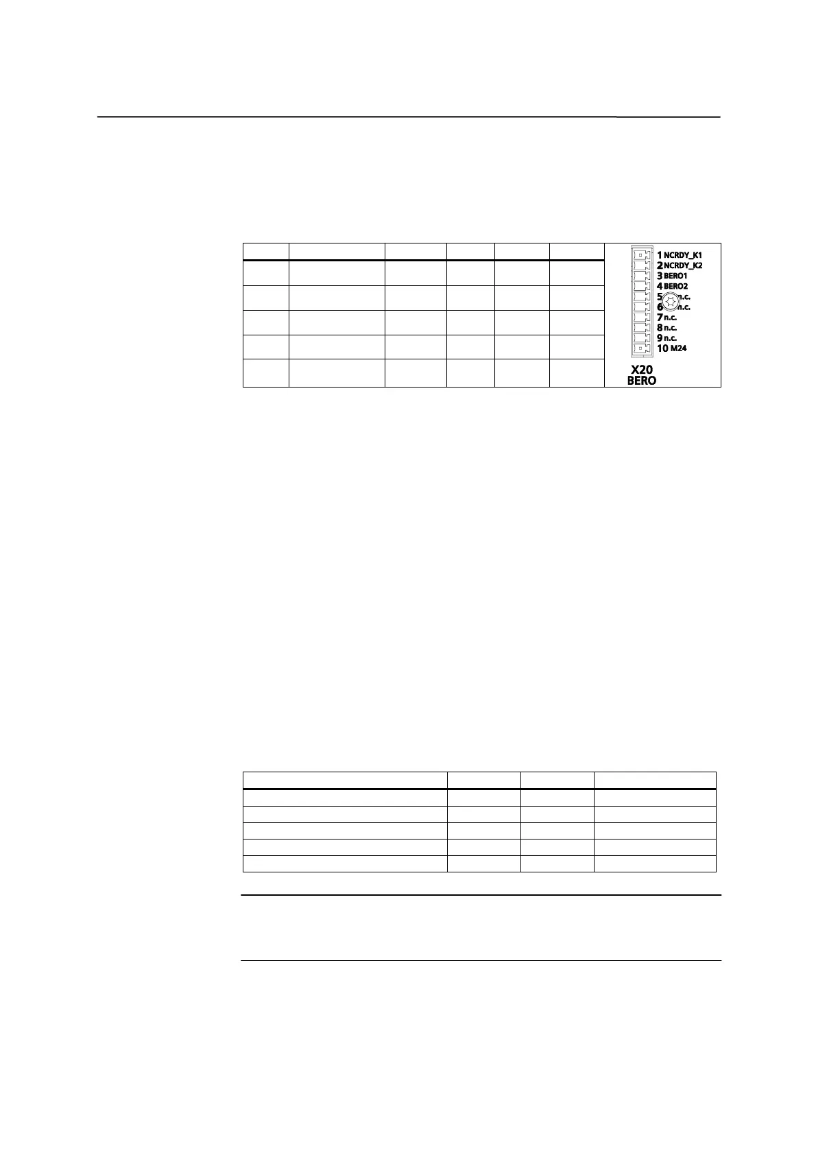
2.3.6 BERO input interface - X20 (BERO)
General Two proximity switches (BERO) can be connected via a 10 pin Mini-Combicon
plug connector X20.
Table 2-12 BERO input interface X20
Pin Signal Type Pin Signal Type
1 NCRDY_K1 K 6 n.c.
2 NCRDY_K2 K 7 n.c.
3 BERO1 DI 8 n.c.
4 BERO2 DI 9 n.c.
5 n.c. 10 M24 VI
Signal Description
NCRDY_K[1 … 2] NC-READY-Relay-Contact, max. current is 2A at
150VDC or 125VAC)
BERO[1 … 2] BERO-Input for axis 1 ... 2
M24 Reference potential for digital input
Signal type
K Switching contact
DI Digital input
VI Voltage input
2 BERO inputs These inputs are 24V PNP-switching. Switches or non-contact sensors, e.g.
inductive proximity switches(BERO) can be connected.
They can be used as switches for reference points, for example:
BERO1 – X axis
BERO2 – Z axis
Table 2-13 Electrical parameters of the digital inputs
Parameter Value Unit Note
“1” signal, voltage range 11 …30 V
“1” signal, current consumption 6 …15 mA
“0” signal, voltage range -3 …5 V Or input open
Signal delay 0Æ1 15 us
Signal delay 1Æ0 150 us
Notice
When AC servo drives are used, BERO can be input as zero mark signals.
However, be careful that here BERO refers to 24V pulse input.
NC–READY output
Readiness in the form of a relay contact (NO); must be integrated into the
EMERGENCY STOP circuit.