Transformations
7.2 Three, four and five axis transformation (TRAORI)
Job planning
Programming Manual, 03/2006 Edition, 6FC5398-2BP10-1BA0
7-21
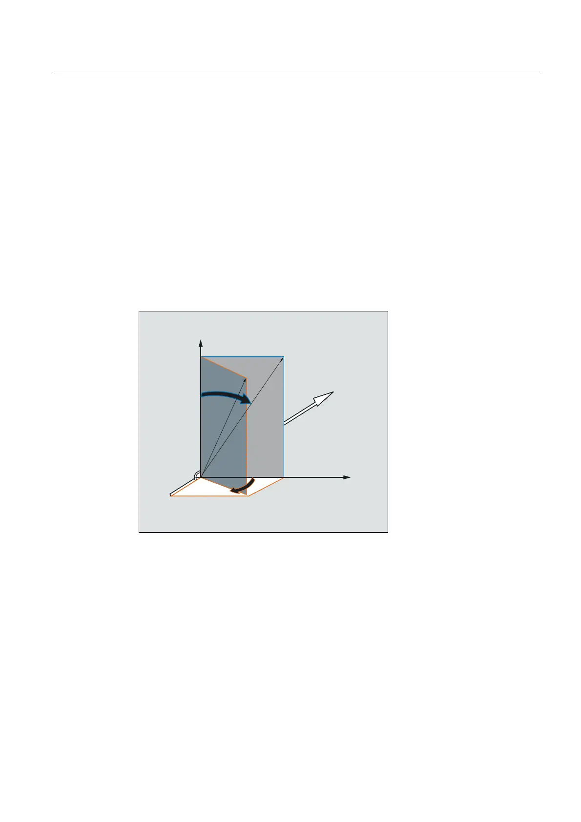
Programming the tool orientation with LEAD= and TILT=
The resultant tool orientation is determined from:
• Path tangent
• Surface normal vector
at the start of the block A4, B4, C4 and at the end of the block A5, B6, C5
• Lead angle LEAD
in the plane defined by the path tangent and surface normal vector
• Tilt angle TILT at the end of the block
vertical to the path tangent and relative to the surface normal vector
Behavior at inside corners (for 3D-tool compensation)
If the block is shortened at an inside corner, the resulting tool orientation is also achieved at
the end of the block.
Definition of tool orientation with LEAD= and TILT=
;
<
=
7,/7
/($'

 Loading...


