4.2 Interfaces
4-54
Copyright © Siemens AG 2006
SINUMERIK 810D Equipment Manual Configuration CCU (PHC) – 03/2006 Edition
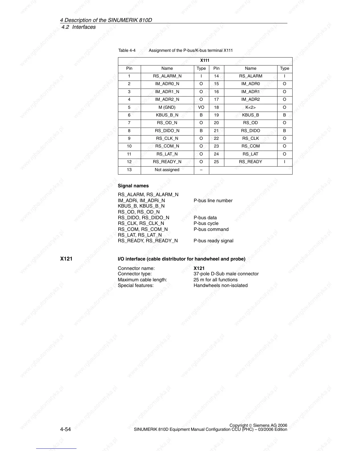
Table 4-4 Assignment of the P-bus/K-bus terminal X111
X111
Pin Name Type Pin Name Type
1 RS_ALARM_N I 14 RS_ALARM I
2 IM_ADR0_N O 15 IM_ADR0 O
3 IM_ADR1_N O 16 IM_ADR1 O
4 IM_ADR2_N O 17 IM_ADR2 O
5 M (GND) VO 18 K<2> O
6 KBUS_B_N B 19 KBUS_B B
7 RS_OD_N O 20 RS_OD O
8 RS_DIDO_N B 21 RS_DIDO B
9 RS_CLK_N O 22 RS_CLK O
10 RS_COM_N O 23 RS_COM O
11 RS_LAT_N O 24 RS_LAT O
12 RS_READY_N O 25 RS_READY I
13 Not assigned –
Signal names
RS_ALARM, RS_ALARM_N
IM_ADRi, IM_ADRi_N P-bus line number
KBUS_B, KBUS_B_N
RS_OD, RS_OD_N
RS_DIDO, RS_DIDO_N P-bus data
RS_CLK, RS_CLK_N P-bus cycle
RS_COM, RS_COM_N P-bus command
RS_LAT, RS_LAT_N
RS_READY, RS_READY_N P-bus ready signal
I/O interface (cable distributor for handwheel and probe)
Connector name: X121
Connector type: 37-pole D-Sub male connector
Maximum cable length: 25 m for all functions
Special features: Handwheels non-isolated
X121
4 Descri