4.2 Interfaces
4-52
Copyright © Siemens AG 2006
SINUMERIK 810D Equipment Manual Configuration CCU (PHC) – 03/2006 Edition
4.2.2 Description of the interfaces, operating and display elements
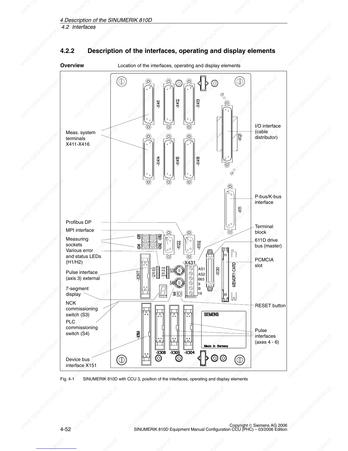
Location of the interfaces, operating and display elements
P-bus/K-bus
interface
MPI interface
I/O interface
(cable
distributor)
Various error
and status LEDs
(H1/H2)
7-segment
display
RESET button
PLC
commissioning
switch (S4)
NCK
commissioning
switch (S3)
611D drive
bus (master)
PCMCIA
slot
Device bus
interface X151
Pulse
interfaces
(axes 4 - 6)
Measuring
sockets
Meas. system
terminals
X411-X416
Terminal
block
Profibus DP
Pulse interface
(axis 3) external
-X431
AS1
AS2
663
9
B
19
CB
PR
PS
PF
PF0
-
+5V
NF
SF
–
Fig. 4-1 SINUMERIK 810D with CCU 3, position of the interfaces, operating and display elements
Overview
4 Descri

 Loading...


