4.2 Interfaces
4-61
Copyright © Siemens AG 2006
SINUMERIK 810D Equipment Manual Configuration CCU (PHC) – 03/2006 Edition
The DIP-FIX switches inside the cable distributor 6FX 2006-1BA01 must be set
as follows:
Table 4-11 Setting the DIP-FIX switches (S1 to S6) in the cable distributor
Switches
S1 S2 S3 S4 S5 S6
Open x x x x
Closed x x
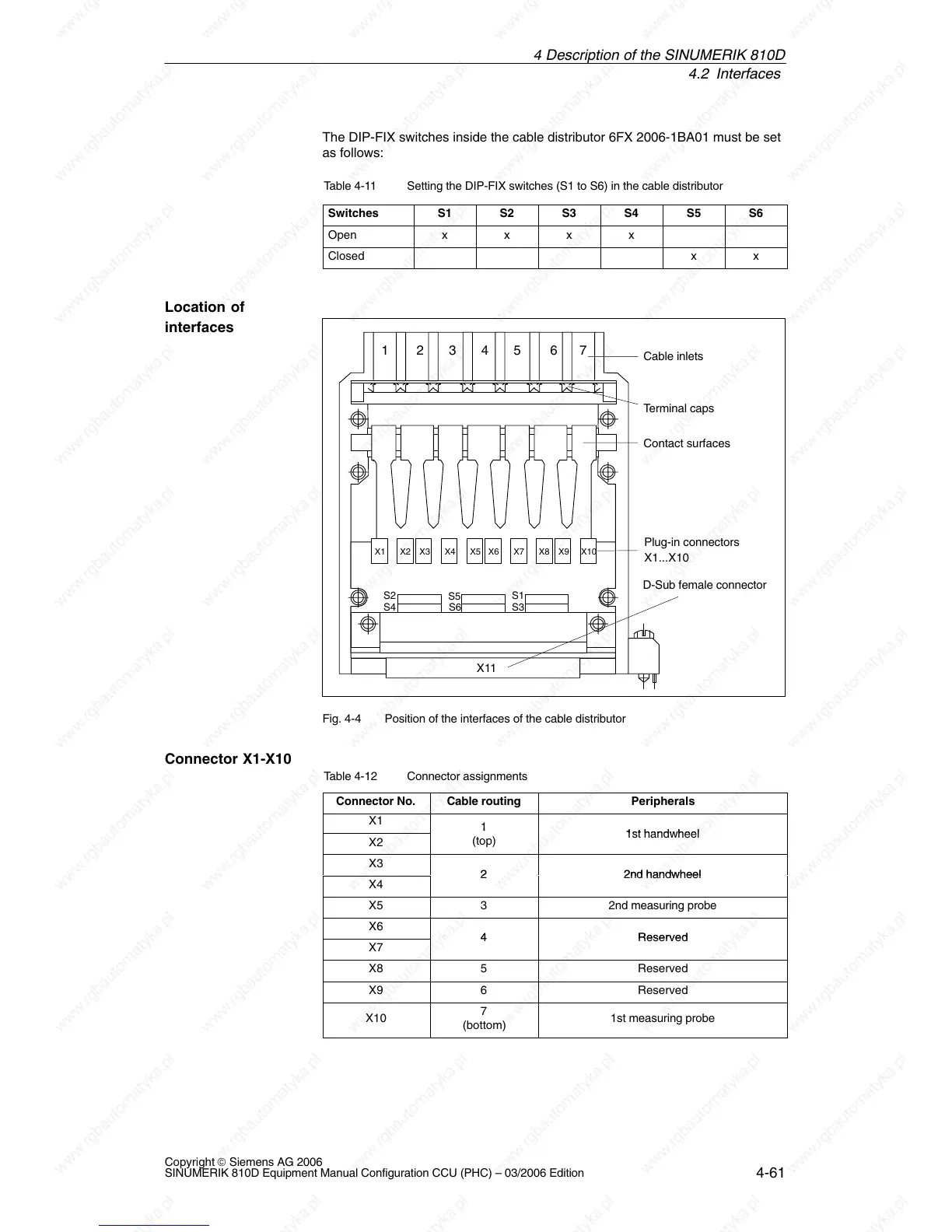
X1 X2 X4 X5 X6 X7 X8 X9 X10X3
X11
Cable inlets
Terminal caps
Contact surfaces
Plug-in connectors
X1...X10
S3S4
S5
S1S2
D-Sub female connector
S6
1 2345 67
Fig. 4-4 Position of the interfaces of the cable distributor
Table 4-12 Connector assignments
Connector No.
Cable routing Peripherals
X1
1
 Loading...


