4.3 Measuring system
4-70
Copyright © Siemens AG 2006
SINUMERIK 810D Equipment Manual Configuration CCU (PHC) – 03/2006 Edition
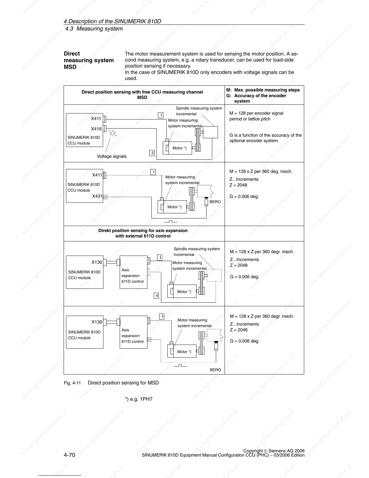
The motor measurement system is used for sensing the motor position. A se-
cond measuring system, e.g. a rotary transducer, can be used for load-side
position sensing if necessary.
In the case of SINUMERIK 810D only encoders with voltage signals can be
used.
Motor *)
Motor measuring
system incremental
BERO
SINUMERIK 810D
CCU module
X411
SINUMERIK 810D
CCU module
Axis
expansion
611D control
X130
Motor *)
BERO
M = 128 x Z per 360 degr. mech.
Z...Increments
Z = 2048
G = 0.006 deg.
M = 128 x Z per 360 deg. mech.
Z...Increments
Z = 2048
G = 0.006 deg.
M: Max. possible measuring steps
G: Accuracy of the encoder
system
Direct position sensing with free CCU measuring channel
MSD
Spindle measuring system
incremental
Voltage signals
X411
X416
M = 128 per encoder signal
period or lattice pitch
G is a function of the accuracy of the
optional encoder system.
SINUMERIK 810D
CCU module
Motor *)
SINUMERIK 810D
CCU module
Axis
expansion
611D control
X130
Motor *)
M = 128 x Z per 360 degr. mech.
Z...Increments
Z = 2048
G = 0.006 deg.
Spindle measuring system
incremental
Motor measuring
system incremental
Motor measuring
system incremental
Motor measuring
system incremental
X431
Direkt position sensing for axis expansion
with external 611D control
1
2
1
1
4
1
Fig. 4-11 Direct position sensing for MSD
*) e.g. 1PH7
Direct
measuring system
MSD
4 Descri
 Loading...


