Table 1-19 Assignment of connector X55
Pin Name Type Meaning
1 KT-IN7
I
Customer key 7
2 KT-IN8 Customer key 8
3 KT-IN9 Customer key 9
4 M V Ground
Optional customer buttons OUT (X53 / X54)
The short-circuit-proof outputs X53/X54 are provided to control lamps in the keys.
Lamps with 24 V and 2.4 W per output are recommended.
;
0*1'
0
3
.7287
.7287
.7287
;
0*1'
0
3
.7287
.7287
.7287
Figure 1-6 Main circuit diagram of the input circuit for X53 and X54
NOTICE
Damage to the electronics
Do not connect any relays, valves or other inductive loads.
Connector designation: X53 / X54
Connector type: 4-pin plug connector
Max. cable length: 0.6 m
Table 1-20 Assignment of connector X53
Pin Name Type Meaning
1 KT-OUT1
O
Output 1 lamp
2 KT-OUT2 Output 2 lamp
3 KT-OUT3 Output 3 lamp
4 M V Ground
General information and networking
1.3 Connecting
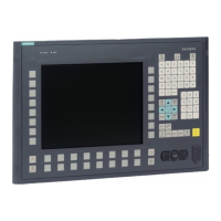
Operator panel front: OP 010
32 Manual, 07/2018, A5E36371538B
 Loading...