Table 1-21 Assignment of connector X54
Pin Name Type Meaning
1 KT-OUT4
O
Output 4 lamp
2 KT-OUT5 Output 5 lamp
3 KT-OUT6 Output 6 lamp
4 M V Ground
Interfaces for two handwheels X60 / X 61
Interface: Handwheel 1 Handwheel 2
Connector designation: X60 X61
Connector type: 15-pin Sub-D socket
Max. cable length: 25 m
Table 1-22 Assignment of connectors X60/X61
Pin Name Type Meaning
1 P5HW V 5 V power supply
2 M V Ground
3 HW1_A / HW2_A I Handwheel pulses track A
4 HW1_XA / HW2_XA I Handwheel pulses track A (negated)
5 N.C. - Not connected
6 HW1_B / HW2_B I Handwheel pulses track B
7 HW1_XB / HW2_XB I Handwheel pulses track B (negated)
8 N.C. - Not connected
9 P5HW V 5 V power supply
10 N.C. - Not connected
11 M V Ground
12 N.C. - Not connected
13 N.C. - Not connected
14 N.C. - Not connected
15 N.C. - Not connected
Note
The handwheels can either be operated with TTL or differential signals.
You set the signal type using S1 (wire bridge) on the COM board.
The handwheels are supplied with 5 V ± 5% and 100 mA via the interface.
Contour and velocity specification via handwheel are not supported.
General information and networking
1.3 Connecting
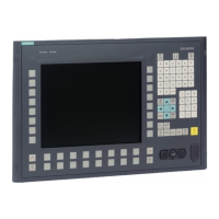
Operator panel front: OP 010
Manual, 07/2018, A5E36371538B 33
 Loading...