Transformations
7.2 Three, four and five axis transformation (TRAORI)
Job planning
Programming Manual, 03/2006 Edition, 6FC5398-2BP10-1BA0
7-17
Parameters
G.... Details of the rotary axis motion
X Y Z Details of the linear axes
A B C Details of the machine axis positions of the
rotary axes
A2 B2 C2 Angle programming (Euler or RPY angle) of
virtual axes or orientation axes
A3 B3 C3 Details of the direction vector components
A4 B4 C4 Details, for example, for the face milling,
the component of the surface normal vector at
block start
A5 B5 C5 Details, for example, for the face milling,
the component of the surface normal vector at
block end
LEAD Angle relative to the surface normal vector in
the plane put up by the path tangent and the
surface normal vector
TILT Angle in the plane, perpendicular to the path
tangent relative to the surface normal vector
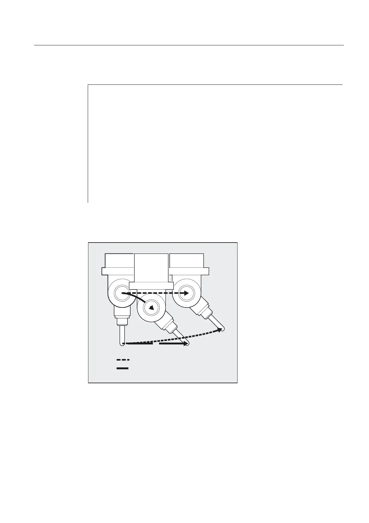
Example: Comparison without and with 5-axis transformation
ZLWKD[LV7UDQVIRUPDWLRQ
ZLWKRXWD[LV7UDQVIRUPDWLRQ
Description
5-axis programs are usually generated by CAD/CAM systems and not entered at the control.
So the following explanations are directed mainly at programmers of postprocessors.
The type of orientation programming is defined in G code group 50:
ORIEULER via Euler angle
ORIRPY via RPY angle (rotation sequence ZYX)

 Loading...


