Tool offsets
8.6 Tool orientation (ORIC, ORID, OSOF, OSC, OSS, OSSE, OSD, OST)
Job planning
Programming Manual, 03/2006 Edition, 6FC5398-2BP10-1BA0
8-31
Programming
A change in tool orientation can be programmed by:
• Direct programming of round axes A, B, C (round axis interpolation)
• Euler or RPY angle
• Direction vector (vector interpolation by specifying A3 or B3 or C3)
• LEAD/TILT (face milling)
The reference coordinate system is either the machine coordinate system (ORIMKS) or the
current workpiece coordinate system (ORIWKS).
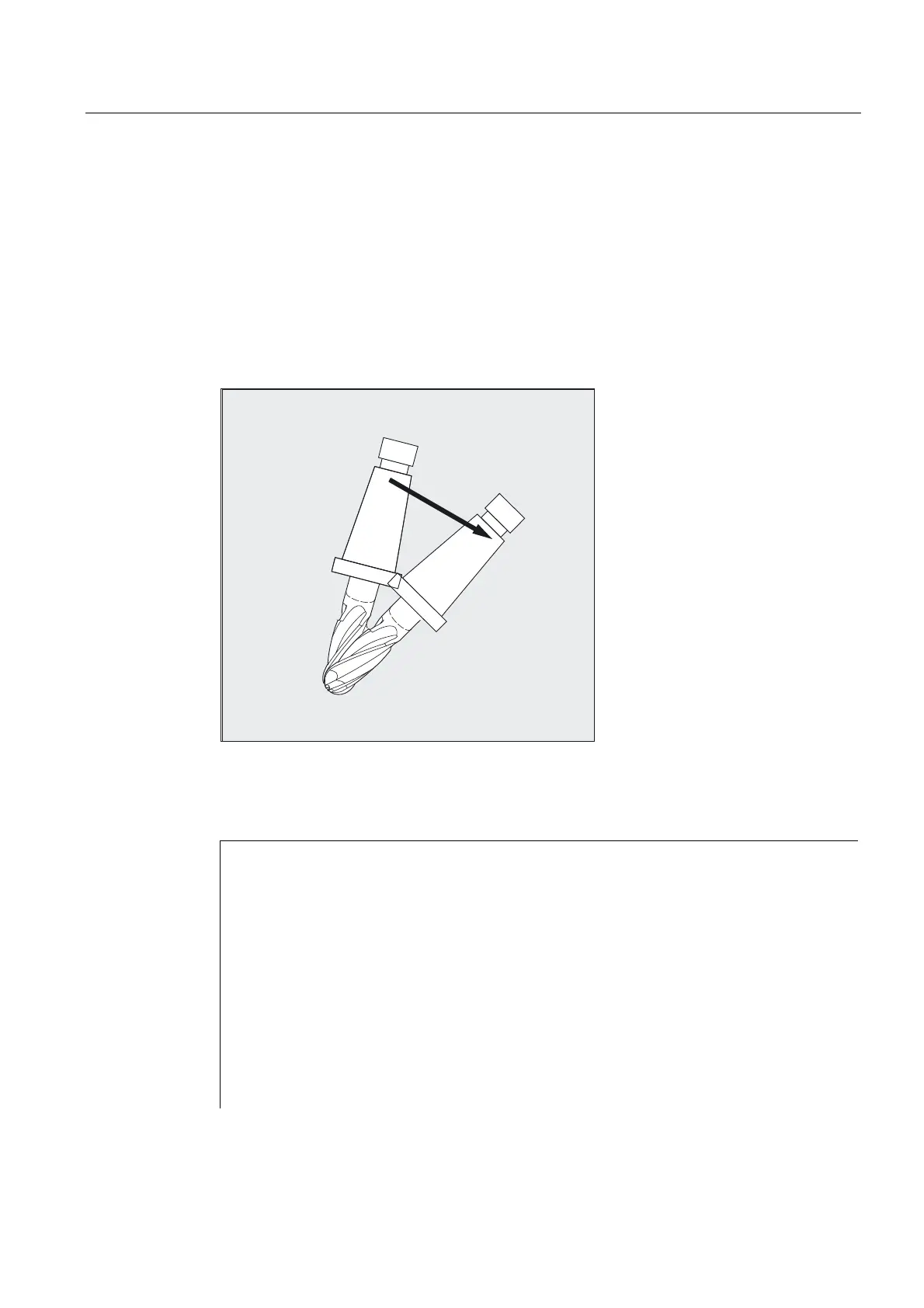
2ULHQWDWLRQ
FKDQJH
Parameters
ORIC Orientation and path movement in parallel
ORID Orientation and path movement consecutively
OSOF No orientation smoothing
OSC Orientation constantly
OSS Orientation smoothing only at beginning of block
OSSE Orientation smoothing at beginning and end of block
ORIS Speed of the orientation change for activated
orientation smoothing in degrees per mm; applies to OSS
and OSSE
OSD Rounding of orientation by specifying rounding length
with SD $SC_ORI_SMOOTH_DIST.
OST Rounding of orientation by specifying angle tolerance
in degrees for vector interpolation with
SD $SC_ORI_SMOOTH_TOL. With round axis interpolation,
the specified tolerance is assumed to be the maximum
variance of the orientation axes.

 Loading...


