Project Planning Manual SIPART DR20
Planning example K1
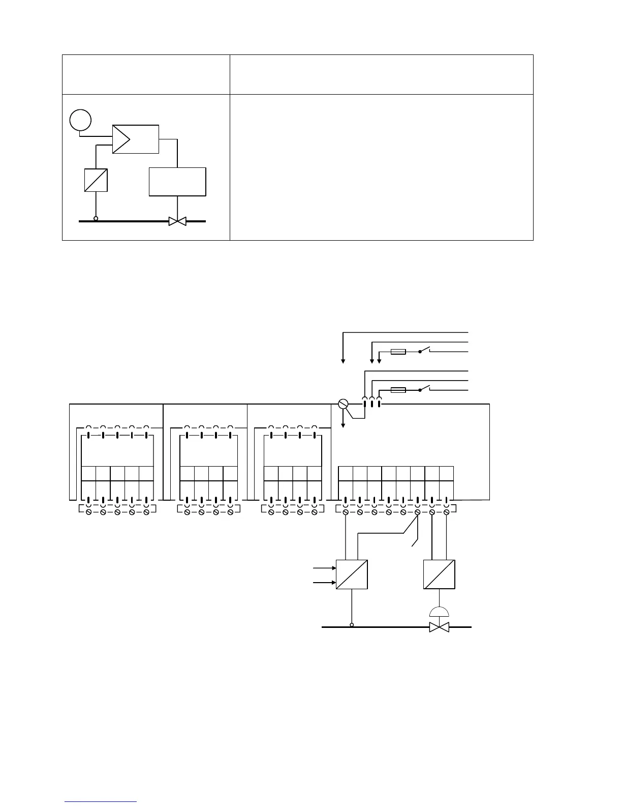
Fixed setpoint control,
controlled variable from four-wire transmitter
W
y
Drive
x
The controlled variable x from the transmitter is applied to
the analog input AE1 of the controller. The programming
corresponds to an input signal range of 0 to 20 mA
The manipulated variable output is also 0 to 20 mA.
The transmitter can be powered from the controller (+ to
terminal 5, -1 to terminaI 6).
The alarm circuit monitors the negative deviation xd for max./
min. deviations (set parameters A2 and A1!).
PIease refer to the remarks on page 108 !
Setting of configuring switches: All configuring switches in factory setting.
AE1 AE2 BE BA L+ GND GND Iy
12345678
SIPART DR20 K
6DR2004-1 (AC 230 V)
6DR2004-2 (AC 115 V)
6DR2004-4 (UC 24 V)
123412341234
PE
N
L
AC 115 V
AC 230 V
⎫
⎬
⎭
PE
N
UC 24 V
L
⎫
⎬
⎭
Slot 3 GW Slot 2 AE4 Slot 1 AE3
5
M1 A1 R1 A2 M2 M M/A S E
I
+
-
y
Option module
6DR2801-8A
not equipped
Transmitter supply
voltage
not equipped
I
+
-
x
112

 Loading...


