Project Planning Manual SIPART DR20
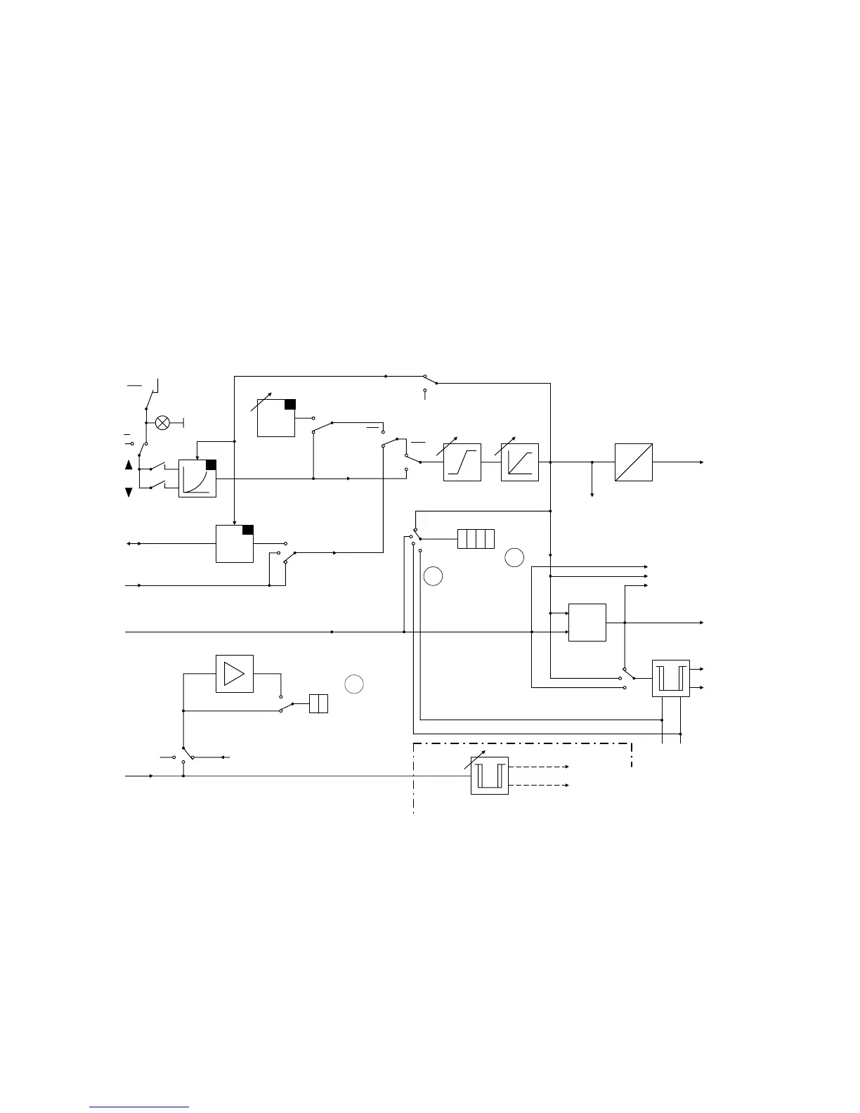
The variable applied to input x1 is indicated as the actual value x. The limit monitors A1/A2 can be
configured to the mentioned variables.
The two-digit display can also indicate a further process variable in %. The associated input signal
is yR / yN.
The station provides further facilities in this mode:
− If the basic device is a K controller, the variable displayed on the four-digit display as setpoint
w is output as a current signal of 0 or 4 to 20 mA via the analogue output. It is a setpoint
transmitter with local/remote switchover in addition.
− If the basic device is an S controller, the signals of a second alarm monitor can be output via
the ± ∆Y outputs. The switching thresholds of this alarm monitor are set by parameters ya
(min.) and ye (max.) with a hysteresis of 1 %. The associated input signal is yR / yN.
X1
w
S
W
ES
SES
S42
0
2
INT
+
INT
gn
SP - w
w
i
ww
X2
1
0
S18
w
i
CB
CB
INT
INT
w
a
w
e
T
w
0
1
S19
U
Ι
S32
Ι
y
1
w
E
y
R
X
00 00
00
0
1
Display
6
S35
1
02
S32
w
S20, S21
Display
Key
8888
8884
+
-
SES
W
X
Xd
0
2
1
S23
A2
A1
a1 a2
+
∆
y (max)
-
∆
y (min)
y
a
min y
e
max
only
S-version
Fig. 3/19 Functional diagram of process indicator (K-version)
42

 Loading...


