Project Planning Manual SIPART DR20
•
S1 = 5 Follow-up controller with local/remote switch over (Fig. 3/13)
This controller type is suitable for SPC mode and operation with two or three setpoints (wi, wE,
wS). The remote setpoint can be entered either via an analog input as a variable wE or via the
serial interface as wES.
In SPC mode the setpoint is tracked by a higher-level computer (control system). SPC mode is
present if the device is switched to remote setpoint and the signal CB is present simultaneously:
NOT(H) AND CB AND NOT(I) = RC = 1
A status LED does not light up in this (normal) case. The green LED 14 flashes with a duty cycle of
0.5 if the computer fails (CB = 1 Æ 0) and further control is made either with the local setpoint wi
which tracked the last valid setpoint (S18 = 0) or with the parameterized safety setpoint wS
(x-tracking is also possible if automatic mode is not present = /A). If the setpoint selector 13 is
activated (INT = 1), the green LED becomes steady and the setpoint can be adjusted manually.
The green LED flashes with a duty factor of 0.9 if the CB signal reappears during local mode but
this mode is retained until a remote setpoint is again selected using pushbutton 13.
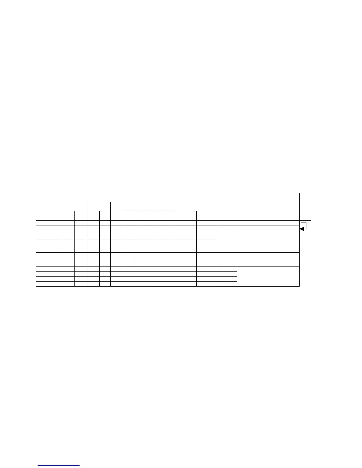
The following table (Fig. 3/10) provides a summary of signals and effective setpoints depending on
control signals and the configuring switches S17, S18 and S19.
Signals
Control commands
front and digital
inputs **)
Front
LED ***)
Digital
output
Effec-
tive
output
Effective setpoint
S19=0
H+N+Si+BL CB INT INT H /RB /RC Y S17=0
S18=0
=1
=0
=0
=1
=1
=1
Explanations
Computer
failure
0 1 0 0 0 0 0 yA(n) wE(n) *) wE(n) *) wE(n) *) wE(n) *) Automatic mode, SPC-mode
0 0 0 0,5 0 0 1 yA(n) wi(n) wi(n) wS wS Automatic mode, computer
switched OFF, controller at SPC
standby
0 1 1 0,9 0 1 1 yA(n) wi(n) wi(n) wi(n) wi(n) Automatic mode, computer at
standby, controller not at SPC
standby
0 0 1 1 0 1 1 yA(n) wi(n) wi(n) wi(n) wi(n) Automatic mode, computer
switched OFF, controller not at
SPC standby
1 1 0 0
>0
1 1 yH or wE(n) *) x wE(n) *) x
1 0 0 0,5
>0
1 1 yE or wi(n) x wS x
1 1 1 0,9
>0
1 1 yS or wi(n) x wi(n) x
1 0 1 1
>0
1 1 yBL wi(n) x wi(n) x
Manual, tracking, safety mode
or blocking of output,
controller not at SPC standby
Fig. 3/10 Follow-up controller with local/remote switchover,
SPC controller with tracking of local setpoint (S19 = 0)
*) Sources for wE are wEA (remote analog value, e.g. from master controller) or wES
(remote value via serial interface). Only wES can be tracked, of course, not wEA
(see Fig. 3/13).
**) When using the digital input BE, only one of the control variables CB, Si, BL or N is possible
as defined by S15. The priority is Si before BL before N (DDC) when applied via the
serial interface.
***) The data on "Signals front LED" (e.g. 0.5) refer to the flashing frequency (see 3.2.6).
(n) The variable is made to track the last value effective before switchover.
NOT(RC) = NOT{NOT(INT) AND CB AND NOT(H)} NOT(RB) = INT OR H
34

 Loading...


