Project Planning Manual SIPART DR20
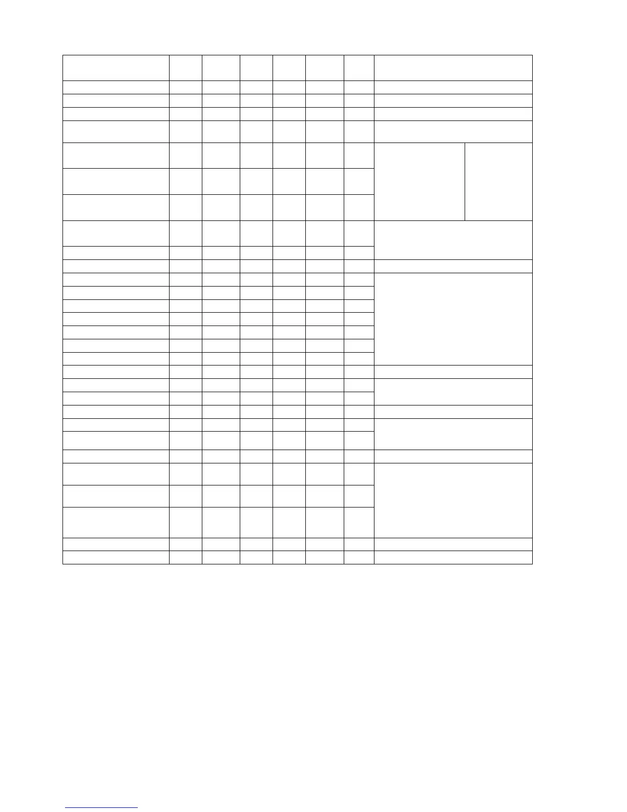
Parameter
Char-
acter
Display
on (6)
Min.
value
Max.
value
Factory
setting
Dim. Remarks
Derivative-action gain Vv “uu” 1.00 10.0 5.00 -
Proportional gain Kp “cP” 0.100 0.100 - 100.0
Reset time “tn” 1.0 9984 s With PI controller S28 = 0 Tn 9984
Working point Yo “Yo” Auto
0.0
99.5 Auto % With P controller S28 = 1
Derivative-action time Tv “tu” OFF
1.00
1000 OFF s
Filter time constant for xd TF "tF" OFF
1.00
1000 OFF s
Setpoint ramp Tw "tS" OFF
1.00
9984
100
OFF s
Tv=Td∗Vv
For S1 ≠ 7/8
For S1 = 7/8
With" oFF" the
D element, the
filter or the
setpoint ramp is
switched off
Valve positioning time /
Period y+
Ty “ty” 1.00 1000 60.0 s
Period y- T- “t-“ -1999 1000 60.0 s
Only for S controllers, T+ / T- apply to the
two output channels with the two-position
controller S2 = 1
Start of scale value 0 % LA “LA” -1999 9999 0.0 -
Vertex 1/8 = 12.5% L1 “L1” -1999 9999 0.0 -
Vertex 2/8 = 25% L2 “L2” -1999 9999 0.0 -
Vertex 3/8 = 37.5% L3 “L3” -1999 9999 0.0 -
Vertex 4/8 = 50% L4 “L4” -1999 9999 0.0 -
Vertex 5/8 = 62.5% L5 “L5” -1999 9999 0.0 -
Vertex 6/8 = 75% L6 “L6” -1999 9999 0.0 -
Vertex 7/8 = 87.5% L7 “L7” -1999 9999 0.0 -
See page 91
The parameters L1 to L7 are only required
for a display of engineering units with
linearization (S14 = 1).
Full-scale value 100 % -1999 100.0 - LE “LE” 9999
Set limitation Start wa 9999 “SA” -1999 -5.0 -
Set limitation End we “SE” -1999 9999 105.0 -
Only values wa/wva ≤ we/wve can be
set.
Safety Setpoint wS “SH” -1999 9999 0.0 -
Alarm value, minimum a2 “A2” -1999 9999 -5.0 -
Alarm value, maximum a1 “A1” -1999 9999 5.0 -
Only values a2 ≤ a1 can be set. With
S24 = 1, a1 and a2 can also be set in the
operating level.
Response threshold of xd A “A” 0.0 10.0 0.0 % Adjust A > 0 with S2 = 2 and 3
Manipulated variable
limitation Start
ya “yA” -10.0 110.0 % -5.0
Manipulated variable
limitation End
ye “yE” -10.0 110.0 105.0 %
Safety manipulated variable ys “yS” -10.0 110.0 0.0 %
Only values ya ≤ ye can be set.
Special features:
S2 = 1 : ya and ye specified dead zone
S2 = 2 : ya/ye ineffective, yS only
0/100 %
S1 = 10 : ya/ye for 2
nd
limit output
min./max.
Constant 1 (zero) c1 “c1” -199.9 199.9 0.0 %
Constant 2 (factor) c2 “c2” -199.9 199.9 0.0 %
Table 6/1 Parameters
90

 Loading...


