SIPART DR20 Project Planning Manual
6. Adjustment and Operation
Operation of the SIPART DR20 controller is carried out at three
modes:
• Process operation
• Parameterization
• Configuring
The pushbuttons and displays on the front of the controller
sometimes have different functions in these three modes.
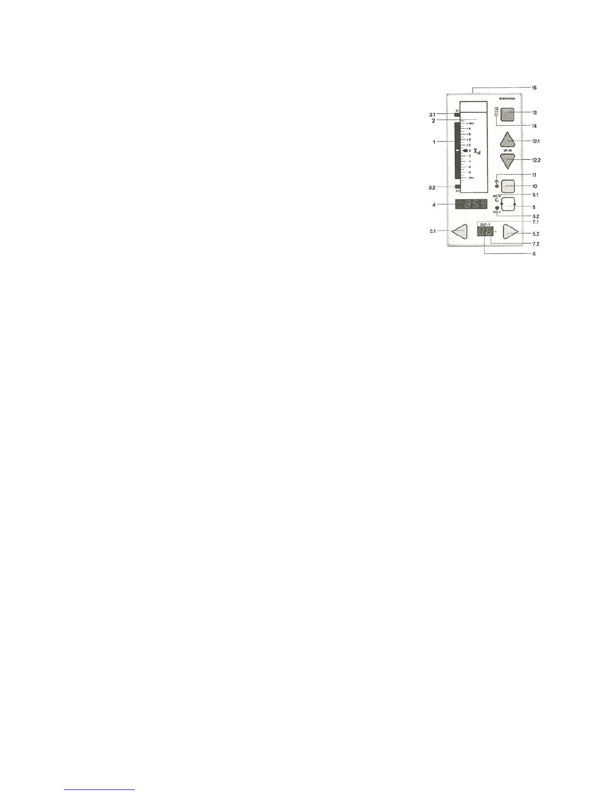
The adjacent photo of the SIPART DR20 front panel corresponds
to Fig.2.1 on page 11.
6.1 Process Operation
Operation of the controller in process mode is self-explanatory as a result of the arrangement and
colors of the front panel, the controls and the inscriptions.
The negative deviation display 1 consists of 21 LEDs; the center LED is green and 10 red LEDs
each light up for the display of + xd or - xd. The sensitivity of the display can be selected in several
stages from ± 2.5 % to ± 40 %.
The associated label 2 can be replaced. The sealing plug 15 at the top of the front frame should be
levered out using a pointed tool and the label can then be pulled out.
Condition on delivery: inscription for scale range ± 10 %.
The rear is not printed and can be inscribed with any scale ranges. The vacant area can be used
for further information, e.g. TAG-number, measuring range, dimension etc.
The LEDs 3 signal downward or upward violation of alarms A1 and A2.
The four-digit, 7-segment display 4 outputs either the setpoint w (green LED 9.1 lights up), the
actual value x (red LED 9.2 lights up) or one of the two alarm values. Output of alarms is signalled
by "A1" or" A2" in display 6. The two variables can be selected using key 8 (see page 35 for
information on a special function of pushbutton 8).
The manipulated variable y is adjusted in manual mode using pushbuttons 5. The rate of
adjustment with K controller increases the longer the button is pressed. In the case of S controllers,
the associated output relay is activated and the point 7 located next to the respective key lights up
in display 6. The two-digit display 6 indicates the output or feedback manipulated variable. The
display range is - 9 to + 109 % (100 % = display "h0", 101 % = display “h1”; etc.). The points 7
signal the output of manipulated variable signals in the case of S controller.
87

 Loading...


