SIPART DR20 Project Planning Manual
∆ U (mV)
1 2 3 4 5
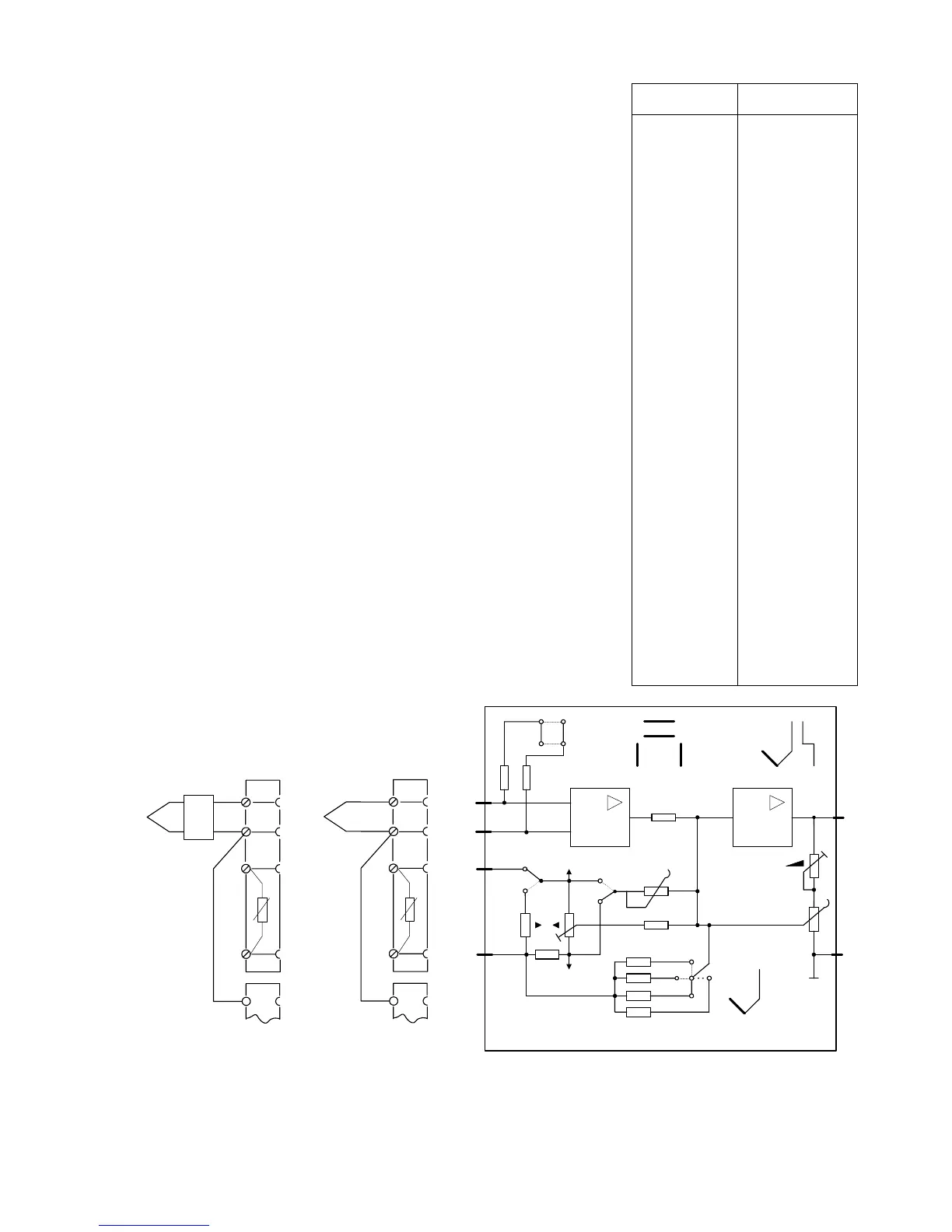
For calibration set jumper from NORM to TEST position. Refer to
thermocouple table DIN 43710 or DIN IEC 584 for value of U
tA
and
U
tE
. Calculate U
0
according to location of cold junction:
The output signal of the module is voltage-linear. The linearization
required with thermocouples to achieve a temperature-linear signal
is carried out using the linearizer which is already included in the
standard controller (see Section 6 for settings).
11.8 - 12.4
12.2 - 13.0
12.7 - 13.3
16.1 - 17.1
55.4 - 58.8
57.9 - 61.6
AB AB AB BC BC
internal 0 °C: U
0
= U
tA
external t
B
: U
0
= U
tA
- U
tB
mV transmitter: U
0
= U
A
Set appropriate jumpers additive to value of U
0
: 0,5 + 1 + 2 + 4 + 8
+ 16 + 32 mV and polarity of U
0
: P (positive) or N (negative).
Calculate ∆U = U
tE
- U
tA
and set jumpers according to table 5/2.
Further jumpers on the module determine whether the input signal
moves towards 0 % or 100 % in the event of a thermocouple
breakage. Tables with the required jumper settings are included in
the SIPART DR20 instructions.
Fine adjustment of the measuring range (start-of-scale value and
span) is carried out using a mV transmitter via the adjustable
resistors accessible at the rear. For operation set jumper to NORM
position for thermocouples using the internal cold junction. Leave it
on TEST for thermocouples using external compensation or mV
transmitters.
9.7 - 10.3
10.1 - 10.7
10.6 - 11.2
11.0 - 11.7
11.5 - 12.0
13.2 - 13.9
13.8 - 14.6
14.4 - 15.0
14.9 - 15.7
15.5 - 16.4
16.7 - 17.3
17.1 - 18.1
18.0 - 19.2
18.9 - 20.0
19.6 - 20.6
20.3 - 21.3
21.2 - 22.5
22.0 - 23.2
23.0 - 24.2
23.9 - 24.9
24.5 - 26.0
25.8 - 27.5
27.3 - 29.0
28.4 - 30.2
30.1 - 31.6
31.4 - 33.4
33.2 - 35.0
34.8 - 36.9
36.8 - 39.2
38.4 - 40.8
40.5 - 43.1
42.6 - 45.2
44.1 - 46.6
46.2 - 49.0
48.8 - 51.4
50.9 - 54.1
53.8 - 56.9
AB AB A BC AB
AB A AB BC AB
A AB AB BC AB
AB AB BC AB AB
AB A A A BC
A AB AB BC A
AB AB BC A AB
A AB A BC AB
AB A BC AB AB
A AB BC AB AB
A AB A BC A
AB A BC A AB
AB BC A AB AB
A A A BC AB
AB BC AB A A
AB AB BC AB BC
BC AB AB AB A
A BC AB AB A
AB BC A A A
AB AB BC BC A
BC AB A AB A
BC A AB AB A
A BC A AB A
AB BC AB BC A
BC AB AB BC AB
AB BC BC AB A
BC AB BC AB AB
A BC AB A BC
BC BC AB AB AB
A AB BC BC BC
BC BC AB A AB
BC A BC BC AB
BC BC AB AB BC
AB BC BC BC BC
BC BC AB A BC
BC BC A AB BC
BC BC BC AB A
BC A BC BC A
BC BC BC BC AB
BC BC A BC BC
BC BC BC BC A
BC BC BC BC BC
+
external
3
4
1
2
6
t
B
internal
+
3
4
1
2
6
R
tu
6DR2800-8T
+ 10 V
∆
U
A B C
+
-
- 10 V
10 M
-
∞
+
-
x ---
>
100 %
x ---
>
0 %
NORM
TEST
R
(0 °C)
0
P
NO
+ U
REF
- U
REF
J, L
R, S
K, T, U
E
Type
1
2
3
4
5
U
0
0.5 ... 32 mV
Fig. 5/8 Wiring of module 6DR2800-8T for thermoelectric voltages / mV
79

 Loading...


