Project Planning Manual SIPART DR20
erfaces
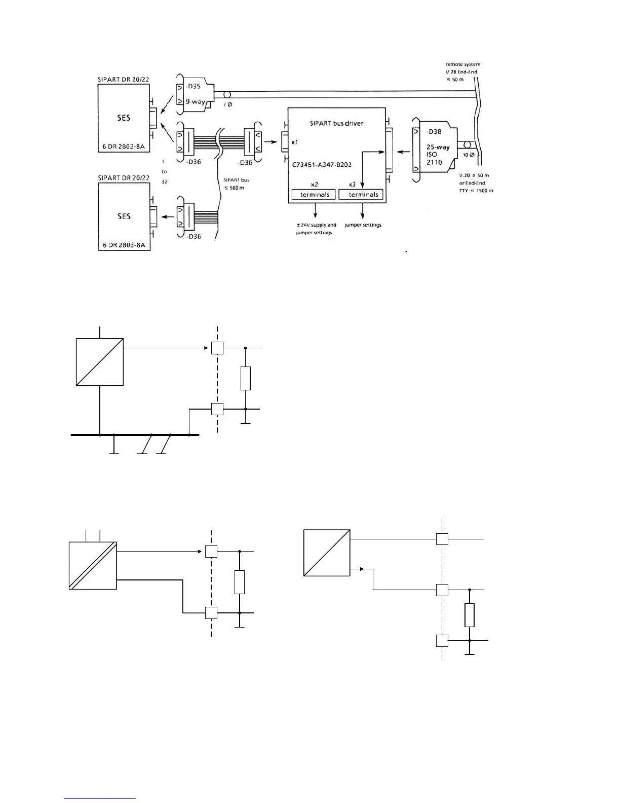
Fig. 5/1 SES and bus driver int
249
Ω
I
+
-
0 (4) to + 20 mA
AE 1 / AE 2
1/2
6
M
U
H
circuit of AE1 or AE2 Connection
with a non-floating current source
249
Ω
I
+
-
0 (4) to + 20 mA
AE 1 / AE 2
1/2
6
M
U
H
249
Ω
I
+
-
0 (4) to + 20 mA
AE 1 / AE 2
M
1/2
5
L +
6
Connection circuit of AE1 or AE2 Connection of a two-wire transmitter to AE1 or
with a floating current source AE2 with power from L+ of controller
Fig. 5/2 Wiring of analog inputs AE1 and AE2
72

 Loading...


