SIPART DR20 Project Planning Manual
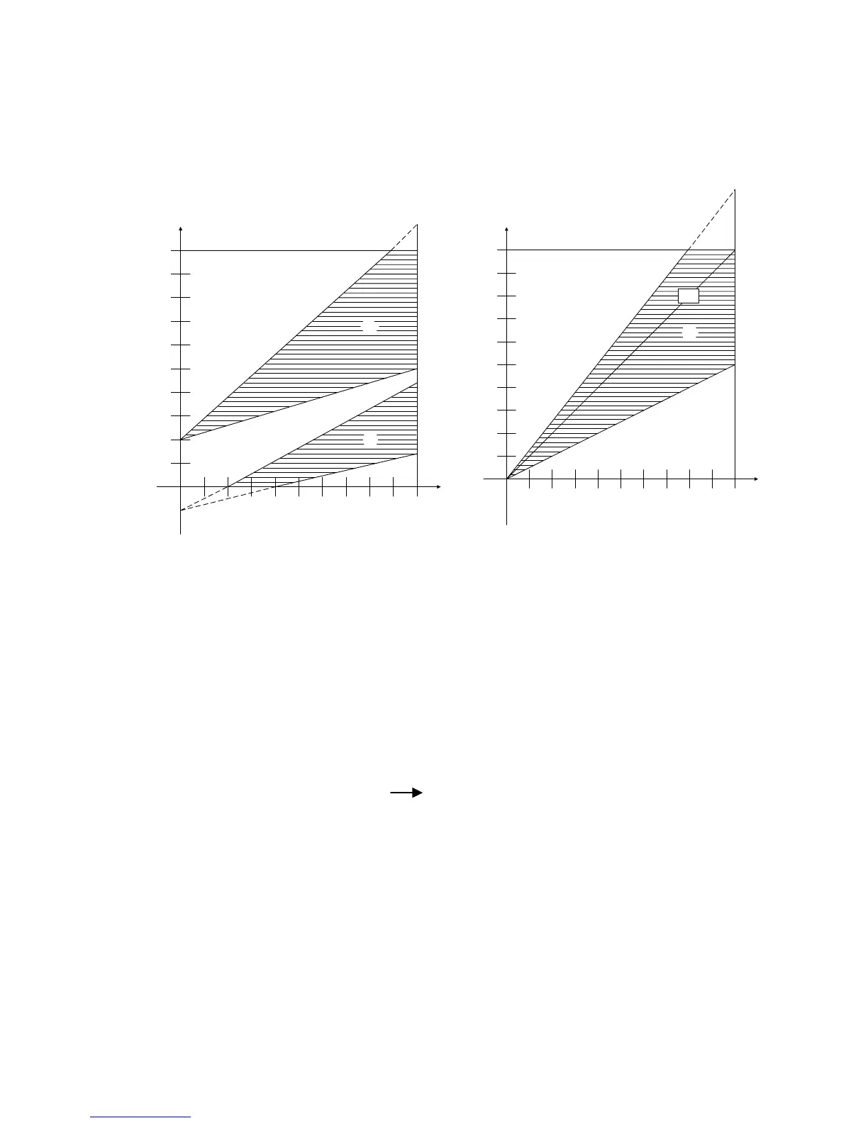
1 Ratio factor Wv = 0,4 to 1,0 3 Ratio factor Wv = 0,5 to 1,5
Basic value 20% = c1 = 0,2
2 Ratio factor Wv = 0,4 to 0,7
Basic value - 15% = c1 = - 0,15
50 100 %
50
100 %
c
d
controlled variable x1
command variable x2
w
va
= 0.4
w
va
= 0.4
w
ve
= 0.7
w
ve
= 1.0
50 100 %
50
100 %
e
controlled variable x1
command variable x2
1.0
w
ve
= 1.5
w
va
= 0.5
Fig. 3/16 Characteristics of a ratio controller
• S1 = 8 Ratio station (Fig. 3/17)
The ratio station can only be implemented with a standard controller with continuous output
(6DR2004)!
Signal processing is exactly the same as in the ratio controller except that the processed command
variable w is processed further directly as the output signal yA:
yA w = v ∗ x2 + c1
This signal is indicated in the two-digit display in percent. The four-digit display indicates, as with
the ratio controller, the ratio factor w
v
which can be adjusted using the setpoint pushbuttons with
selector 8 in position "SP-w". As with the ratio controller, the range of adjustment for the ratio factor
is determined using the parameters w
a
and w
e
within the limits 0.000 and 9.999 where LA < w
a
and
LE > w
e
.
The actual ratio x
v
is only indicated in position "PV-x" of selector 8 if the controlled process variable
x1 is also applied to the controller. In this case the negative deviation xd = w - x1 is also displayed
on the 21-part LED bargraph.
39

 Loading...


