Project Planning Manual SIPART DR20
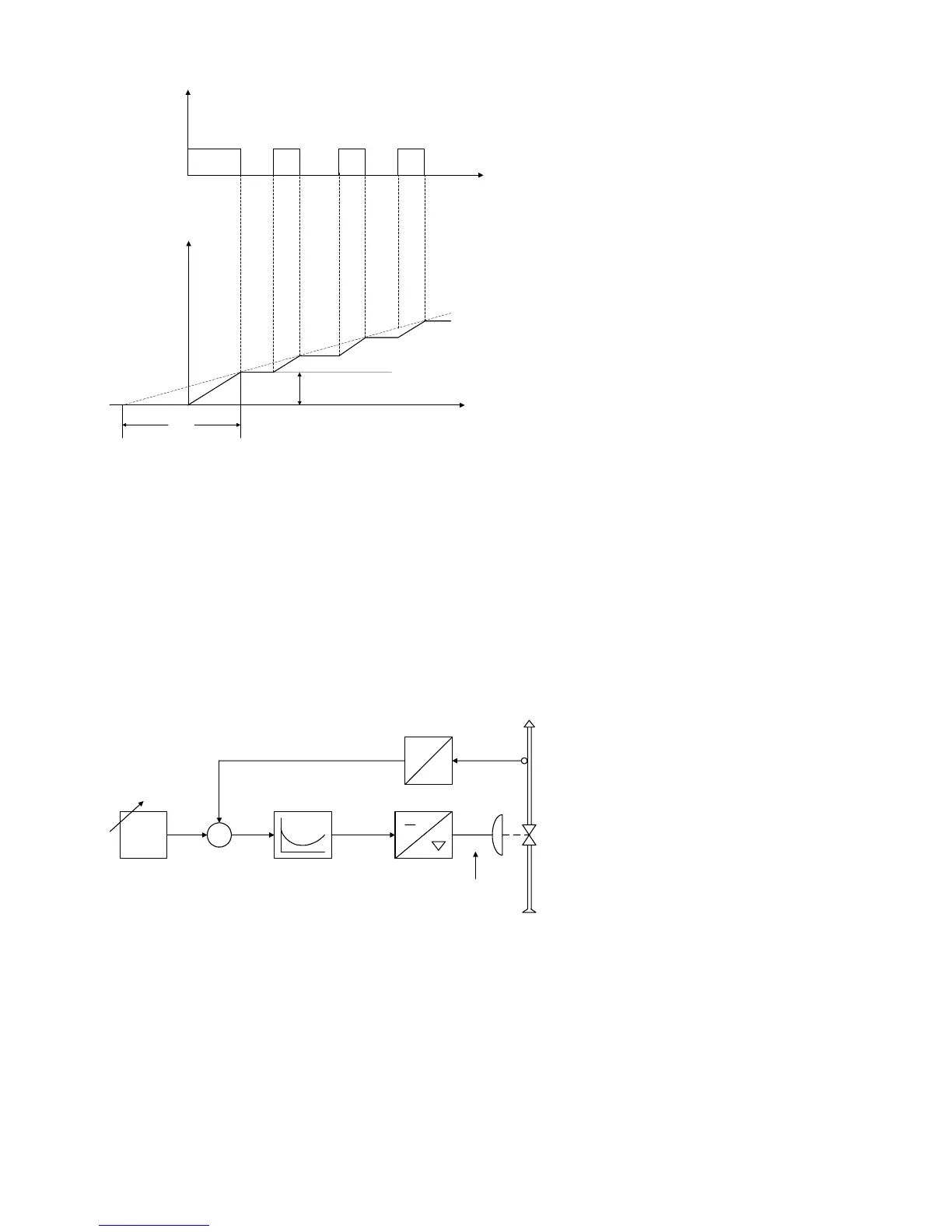
y
∆y
t
t
Kp ∗ xd
Tn
Kp Proportional gain
Tn Reset time
xd Negative deviation
∆y Manipulated variable
(controller)
y Manipulated variable
(motor)
Fig. 1/4 Three-position step controller,
transient function and parameters
The transient function produced at the final control element by these pulses resembles that of a
continuous PI controller. Therefore the parameters Kp and Tn are also applied to the description of
the transient function of three-position step controllers. This is referred to as quasi-continuous
control (see Fig. 1/4).
The response threshold A is adjustable in our controllers. Thus, for example, noise suppression
and a stabilizing effect can be achieved.
The main field of application of continuous controllers is in installations with pneumatic
actuators. The controller output signal of 0 to 20 mA or 4 to 20 mA acts continuously on the final
control element through an electropneumatic signal converter.
w
32
x
-
+
xd
4
1
y
0.2 ... 1.0 bar
y
x
5
0 ... 20 mA
(4 ... 20 mA)
w Command variable
x Controlled variable
xd Negative deviation
1 Transmitter
2 Setpoint adjuster
3 Control amplifier
4 Electropneumatic
signal converter
5 Pneumatic final
control element
Fig. 1/5 Continuous controller,
functional diagram
Two-position or three-position controllers are used to activate relays, contactors or thyristor
switches for switching electric heaters or coolers. The two-position controller (Fig. 1/6) switches, if
the controlled variable goes below the value x1 or above x2. A continuous oscillation occurs whose
frequency depends on the delay time of the controlled system and the switching hysteresis of the
controller.
8

 Loading...


