SIPART DR20 Project Planning Manual
Cofiguring
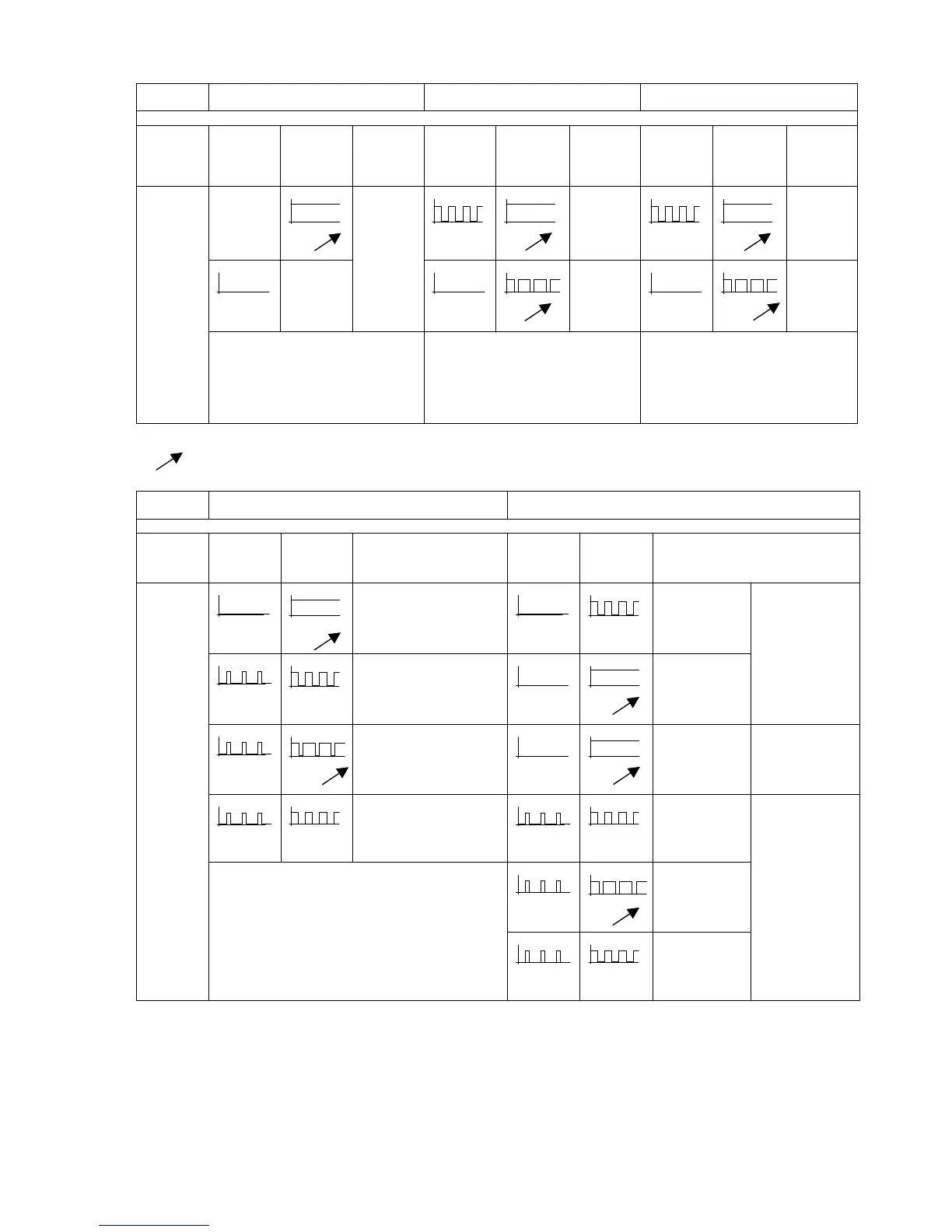
switch Æ
S1 = 0, 1, 2, 7, 8 S1 = 5, 10 S1 = 3, 9
Selected
function
/INT
w -adjust-
ment
blocked
INT
local
mode
/INT
remote
mode/SPC
INT
local
mode
/INT
DDC
backup
mode
INT
controller
mode
wi
S18=0 : wi
S18=1 : wS
wi
CB=0
automatic
wi
automatic
wi
CB=0
wi
CB without
function
wE
wi
CB=1
backup
S18=0 : wi
S18=1 : wS
automatic
wi
CB=1
W - LED
w
effect
x-tracking: S17 = 1
S18 = 0
S19 = 0
x-tracking: S17=1 *)
wS: S18=1 effective with (/INT AND /CB)
wi-tracking: S19=0 the inactive wi is tracked
to the effective setpoint w (wS, wE)
x-tracking: S17=1
not with local operation mode
wS: S18=1 effective with (/INT AND /CB)
*) Æ not with S1=10
adjustable
Cofiguring
switch Æ
S1 = 0, 1, 2, 4, 5, 6, 7, 8, 10 *) S1 = 3, 9
Selected
function
/H (A)
automatic
mode
H
manual
mode
/H (A)
automatic
mode
H
manual
mode
yA
yH
N / Si / BL = 0
yE
yE
S29 = 0
Si / BL = 0
yBL, yN
yBL, yN
S29 = 0
BL / N = 1
yE
yH
S29 = 1
Si / BL = 0
DDC backup mode
yBL, yN
yH
S29 = 1
BL / N = 1
yA
yH
Si / BL = 0
Controller mode
yS
yS
Si = 1
yS
yS
Si = 1
yBL
yH
S29 = 1
BL = 1
H - LED
y
effect
*) The H/A switchover (MAN/AUTO) is not effective
with S1=10
the H-LED is OFF
yBL
yBL
S29 = 0
BL = 1
All operation modes
(via SES)
Fig.3/34 Optical signalling and effective variables with different functions/operating states
59

 Loading...


