Project Planning Manual SIPART DR20
Planning example K9
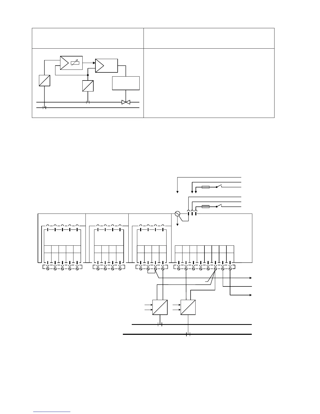
Ratio control
with a ratio station and a slave controller
y
Drive
x1
x2
W
v
Y = v ∗ x2 + (± c1)
The controlled variable x2 from a four-wire
transmitter is linked to the analog input AE2 of the
ratio station. The output signal follows the formula:
and is applied to the slave controller as remote
setpoint w. The ratio factor wv (page 38) is indicated
in display 4 as setpoint.
PIease refer to the remarks on page 108 !
Setting of configuring switches of the ratio station:
S1 = 8, S8 = 1, S10 = -1, S25 = OFF
AE1 AE2 BE BA L+ GND GND Iy
12345678
SIPART DR20 K
6DR2004-1 (AC 230 V)
6DR2004-2 (AC 115 V)
6DR2004-4 (UC 24 V)
123412341234
PE
N
L
AC 115 V
AC 230 V
⎫
⎬
⎭
PE
N
UC 24 V
L
⎫
⎬
⎭
Slot 3 GW Slot 2 AE4 Slot 1 AE3
5
M1 A1 R1 A2 M2
not equipped
Option module
6DR2801-8A
M M/A S E
I
+-
+
-
x2
Ratio station
Option module
6DR2800-8J
x1
I
+
-
+
-
120

 Loading...


