Project Planning Manual SIPART DR20
Planning example K10
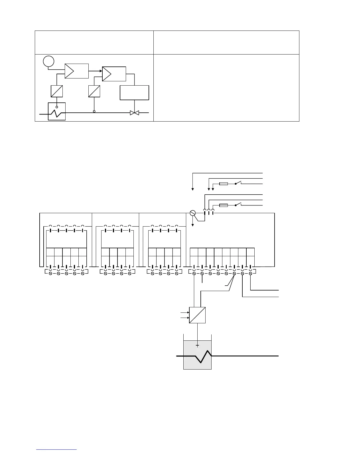
Cascade control
Controlled variables for both controllers from
four-wire transmitters
W
y
Drive
xFo
Slave
Master
The controlled variables x1 and x2 are connected to
the inputs AE1 of the respective controllers. The
output signal of the master controller is the remote
setpoint of the slave controller and linked to its
analog input AE2.
Please refer to the remarks on page 108!
Setting of configuring switches: AIl configuring switches in factory setting
AE1 AE2 BE BA L+ GND GND Iy
12345678
SIPART DR20 K
6DR2004-1 (AC 230 V)
6DR2004-2 (AC 115 V)
6DR2004-4 (UC 24 V)
123412341234
PE
N
L
AC 115 V
AC 230 V
⎫
⎬
⎭
PE
N
UC 24 V
L
⎫
⎬
⎭
Slot 3 GW Slot 2 AE4 Slot 1 AE3
5
M1 A1 R1 A2 M2
not equipped
M M/A S E
not equipped
I
+
-
+
-
x1
Master controller
not equipped
122

 Loading...


