Project Planning Manual SIPART DR20
Structuring
switches
and
positions
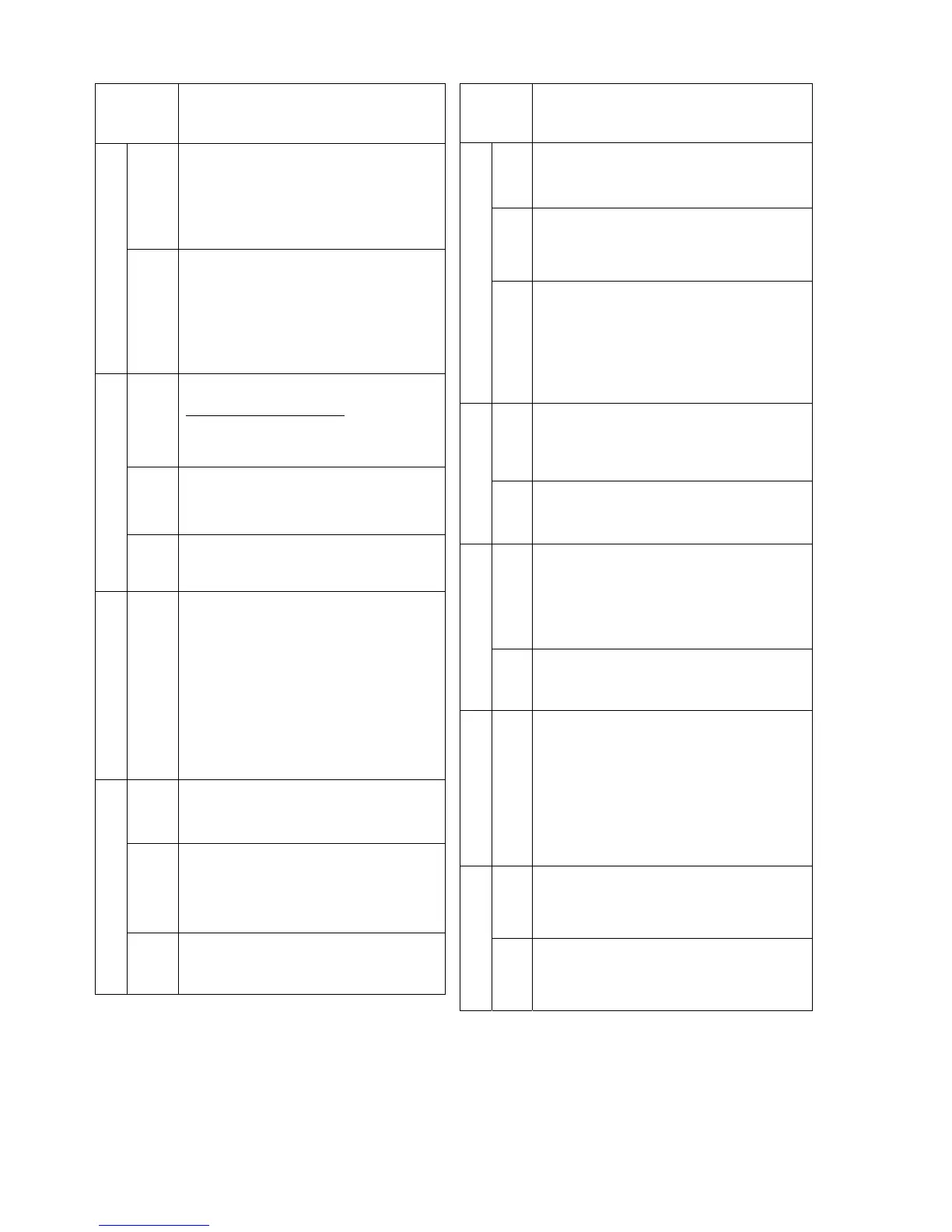
Function
S20
-1
0
1
2
Decimal point in display 4 for SP-PV-A2-A1
(ineffective with S1=7 and 8)
x x x x
x x x. x
x x. x x
x. x x x
Display
S21
-3
-2
-1
0
1
2
OFF
Repetition rate of the digital display:
0.1 sec
0.2 sec
0.5 sec
1.0 sec
2.0 sec
5.0 sec
display 4 switched OFF, indicator 6: 0.1 sec
S22
0
1
2
Input of the limit monitors:
S1 = 0 to 6, 9, 10 ⏐ 7, 8____
Xd ⏐ Wv – Xv
2)
X ⏐ Xv
W ⏐ Wv
S23
0
1
2
Function of the alarm monitors:
A1 = max. and A2 = min.
A1 = min. and A2 = min.
A1 = max. and A2 = max.
Alarm signalling
S24
0
1
Setting the alarm monitors:
Only in the parametrization level
Also in the process operation level
Xd display
S25
-2
-1
0
1
2
OFF
3
4
5
6
7
Display range of the display 1:
± 2.5 %
± 5.0 %
± 10 %
± 20 %
± 40 %
Display switched OFF
± 40 %
± 20 %
± 10 %
1)
± 5.0 %
± 2.5 %
S26
0
1
Sense of the controller in the controlled system
Normal (cP > 0) referred to
Reversed (cP < 0) Xd = w-x
S27
0
1
2
3
D element input
Xd
X
X2/W
E
direction of action against X
X2/W
E
direction of action with X
Algorithm
S28
0
1
Control algorithm
PI (D)
P (D)
Structuring
switches
and
positions
Function
S29
0
1
Priority N (DDC), BL or H:
N (DDC), BL
H
S30
0
1
2
Manual mode with transmitter fault (S11):
Switchover does not take place to manual mode
Starts with last manipulated variable
Starts with safety manipulated variable
Output switchover
S31
0
1
2
Blocking of the manual/automatic switchover:
No
Only automatic operation, switchover to manual
mode not possible
Only manual operation with interlocking (the ∆y
readjustment facility can be switched off by key
10,
LED 11 then does not light up)
S32
0
1
OFF
Manipulated variable display:
Control output Y
Feedback signal Y
R
No display
Y Display
S33
0
1
Sense of position display on the controlled system
Normal (Y-display = Y or Y
R
)
Reversed (Y-display = 100%-Y or 100%-Y
R
)
S34
0
1
2
3
4
Function of the digital output BA:
/RC Controller not in computer mode
H Controller in manual mode
/RB Controller not in computer standby
MuSt Transmitter fault
BA is activated via the serial interface
Digital output BA
S35
0
1
Sense of the digital output BA:
Logical 1 = 24 V
Logical 1 = 0 V
Alarm components
S36
0
1
Components supplied with the optional module
GW:
Alarm outputs:
Controller supplied with module 6DR2801-8A Æ 2
relays for A1/A2, or GW is not used
Controller supplied with module
6DR2801-8B Æ 4 digital outputs for A1, A2 and
± ∆y, and 1 digital input for blocking of parame-
terization and structuring (the relay outputs ± ∆y of
basic device have no function)
S37
0
1
Current output Iy of the K controller
(only with S2 = 0):
0 to 20 mA
4 to 20 mA
K controller
S38
0
1
Iy switch-off with DDC operation
(only with S2 = 0 and S1 = 3 or 9):
No
Yes
Table 3/1 Configuring switches (continued)
1)
Software release – A08 or greater
2)
Software release – A09 or greater
20

 Loading...


