Project Planning Manual SIPART DR20
Selector key 8 Output in display 4 Signalling by
Position 1 wi LED 9.1
Position 2 x LED 9.2
Position 3 A2 "A2" in display 6
Position 4 A1 "A1" in display 6
Position 5 wS "SH" in display 6
This results in the following possible settings:
Signals
Control commands
front and digital
inputs **)
Front
LED ***)
Digital
output
Effec-
tive
output
Effective setpoint
Explanations
H+N+Si+BL INT INT H /RB /RC Y S17=0
S17=1
0 1 1 0 1 1 yA(n) wi wi Automatic mode with setpoint 1
0 0 0,5 0 0 1 yA(n) wS wS Automatic mode with setpoint 2
1 1 1
>0
1 1 yH, yN wi x
1 0 0,5
>0
1 1 yBL, ySi wS x
Manual, tracking, safety mode or blocking of output
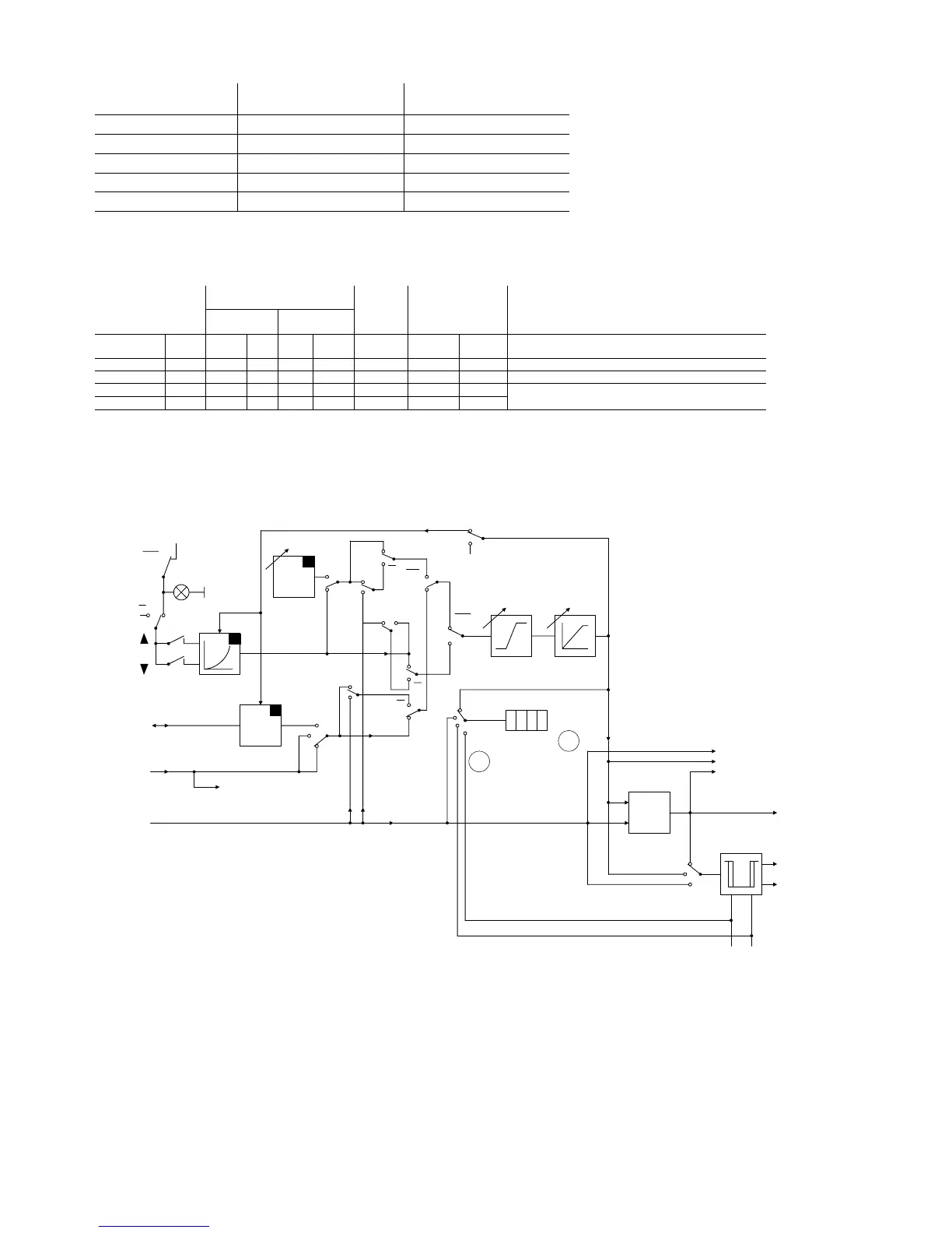
Fig. 3/12 Follow-up controller with local/remote switchover
Operation with two setpoints adjustable on front panel
X1
w
S
W
ES
SES
S42
0
2
INT
+
INT
gn
SP - w
w
i
ww
X2 / W
EA
1
0
S18
w
i
CB
CB
INT
INT
w
a
w
e
T
w
0
1
S19
1
w
E
X
00 00
S20, S21
Display
Key
8888
8884
+
-
SES
W
X
Xd
0
2
1
S23
A2
A1
a1 a2
D-element
S17
A
A
1
0
01
A
A
A
A
S17
0
1
x - tracking
Fig. 3/13 Processing of command variable and formation of negative deviation in follow-up
controller with local/remote switchover
36

 Loading...


