Project Planning Manual SIPART DR20
3
1
2
4
6DR2800-8J
+
-
49.9
Ω
Ι
AE3 / AE4
+
-
6
M
Standard controller
4 to 20 mA AE +
AE -
5
L +
1)
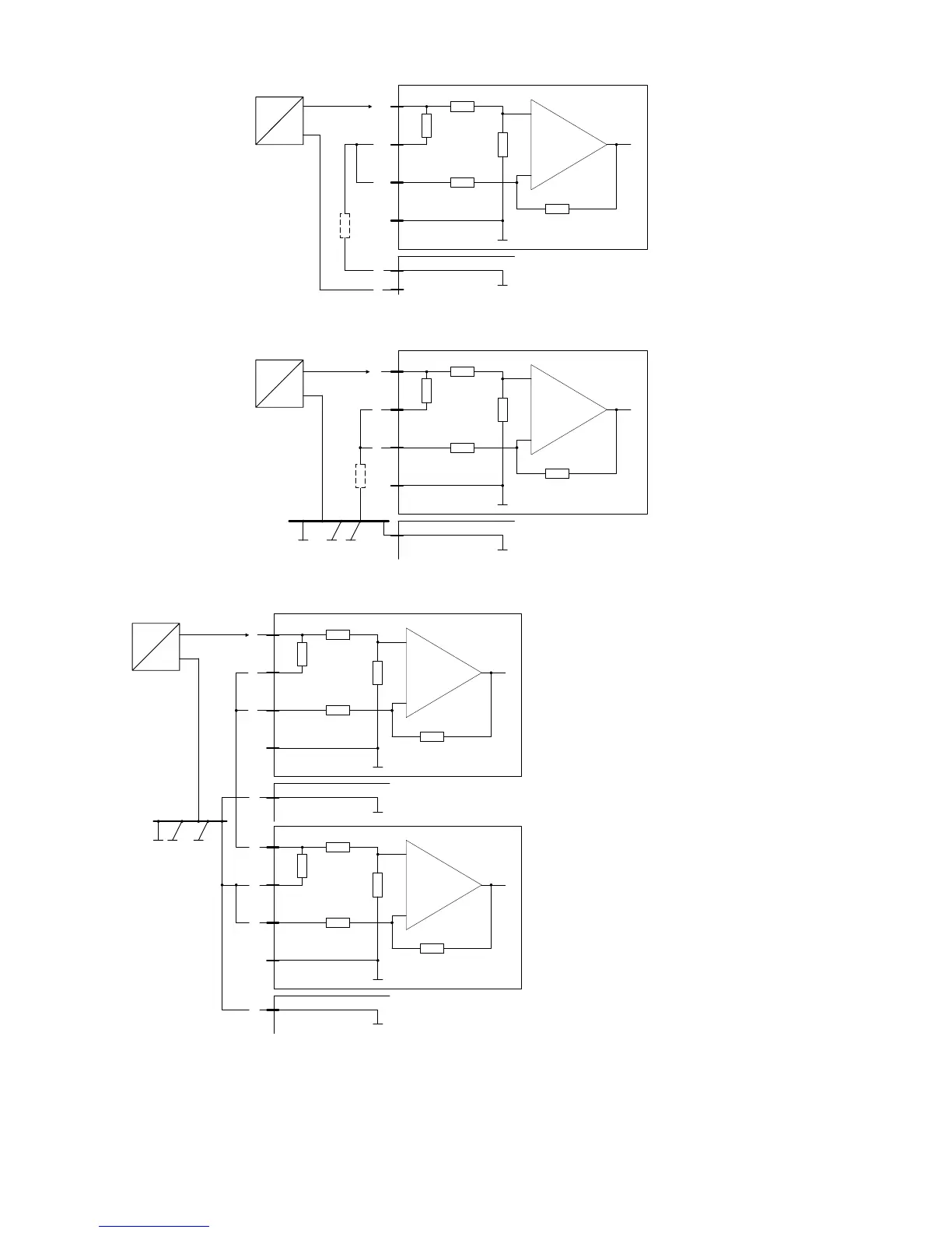
Connection of a two-wire transmitter to a signal converter 6DR2800-8J. The transmitter is powered by L+ of the controller:
3
1
2
4
6DR2800-8J
+
-
49.9
Ω
Ι
AE3 / AE4
+
-
6
M
Standard controller
AE +
AE -
0 (4) to 20 mA
1)
Connection circuit of signal converter 6DR2800-8J as current input with a non-floating current source of 0 to 20 or 4 to 20 mA.
3
1
2
4
6DR2800-8J
+
-
49.9
Ω
AE3 / AE4
6
M
Standard controller
AE +
AE -
3
1
2
4
6DR2800-8J
+
-
49.9
Ω
AE3 / AE4
6
M
Standard controller
AE +
AE -
Ι
+
-
0 (4) to 20 mA
Device 1
Device 2
1) The common-mode voltage may be
up to + 10V. A total resistance
against the reference potential is
therefore permissable up to 500
Ω
at this position. Note the minimum
operating voltage of the two-wire
transmitter.
Series connection of 2 current inputs with signal converter 6DR2800-8J. Both controllers must be connected to a common ground.
Controller 2 could also be an analog input AE1 or AE2.
Fig. 5/4 Wiring of module 6DR2800-8J for current signals
74

 Loading...


