Operation
102
SIPAR T PS2 Manual
A5E00074631--06
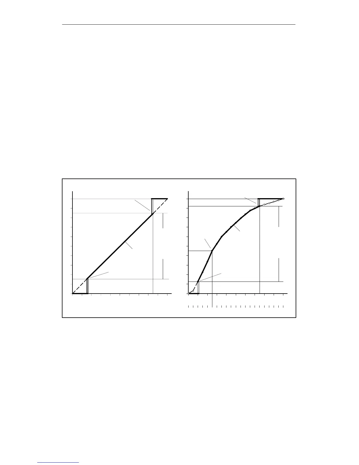
Six valve characteristics are stored in the positioner
S linear (12.SFCT = Lin, factory setting)
S equal percentage 1 : 25 (12.SFCT = 1:25)
S equal percentage 1 : 33 (12.SFCT = 1:33)
S equal percentage 1 : 50 (12.SFCT = 1:50)
S inverse equal percentage 25 : 1 (12.SFCT = n1:25)
S inverse equal percentage 33 : 1 (12.SFCT = n1:33)
S inverse equal percentage 50 : 1 (12.SFCT = n1:50)
S freely adjustable (12.SFCT = FrEE)
Setpoint turning points
A flow parameter can be assigned to the respective setpoint turning
value at an interval of 5 %. These points lead to a polygon chain with
20 straight lines which therefore represents a projection of the valve
characteristic.
w
x
10
20
30
40
50
60
70
80
90
100%
100
0
20 30 40 50 60 70 80 90 100 %
9SFCT=Lin
Modulation range
w
x
10
20
30
40
50
60
70
80
90
100%
100
0
20 30 40 50 60 70 80 90 100 %
2106141941217816195131831171520SL 0
12 SFCT = FrEE
Limit for tight closing
Example:
39 YCLS = UP
41 YCUP = 85.0
Limit for tight closing
Example:
39 YCLS = UP
41YCUP = 75.0
Limit for tight closing
Example:
39 YCLS = DO
40YCDO = 10.0
Limit for tight closing
Example:
39 YCLS = DO
40 YCDO = 15.0
Setpoint turning point
Example:
18 SL5 = 45.0
Modulation range
Setpoint
Setpoint
Figure 4-9 Setpoint characteristic, manipulated variable standardization and tight closing function
The setpoint vertex values can only be input at 12.SFCT=FrEE. You
may only enter a strictly monotonous characteristic, and two consecu-
tive vertex values must differ by at least 0.2 %.
13.SL0 to 33.SL20

 Loading...