Design and Functional Principle
18
SIPAR T PS2 Manual
A5E00074631--06
8
9
6.2
6.1
10
3
7
----
++
1
10
138238 9
2121
45
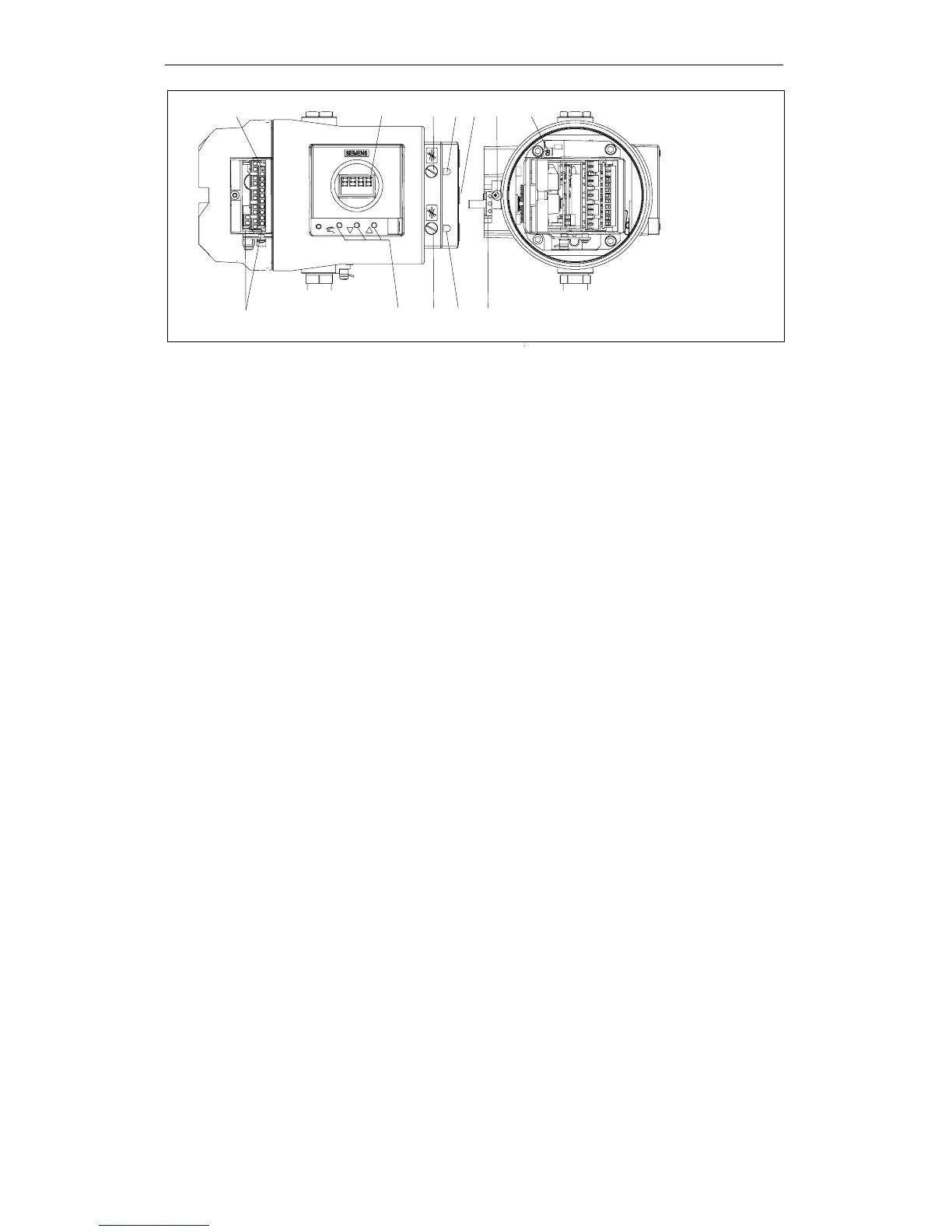
1 Input: Supply air 7 Transmission ratio selector
2 Output: Actuating pressure Y1 (only possible with positioner open)
3 Display 8 Adjusting wheel for friction clutch
4 Output: Actuating pressure Y2
*)
9 Terminals standard controller
5 Operating keys 10 Terminals options modules
6.1 Restrictor Y1 12 Safety catch
6.2 Restrictor Y2
*)
*)
in double-acting actuators
Figure 2-3 View of the explosion proof version of the positioner
2.3.1 Motherboard
The motherboard contains all the electronic elements such as the CPU,
memory, A/D converter . It also contains the display and the operating
keys.
In addition, the terminal strips for connecting the options modules are
also on the motherboard.
2.3.2 Electrical Connection s
The terminals of the standard controller, the I
y
- and alarm-option mod-
ule are arranged at the left-hand front edges and offset against each
other in staircase form.
A module cover protects the modules from being pulled out and pre-
vents incorrect installation.

 Loading...