Preparing for Operation
52
SIPAR T PS2 Manual
A5E00074631--06
4)
8
1
10
11
7
21
11
10
11
as required
Mounting on yoke
with columns
Mounting on yoke
with plane surface
8
10
Mounting on yoke
with ledge
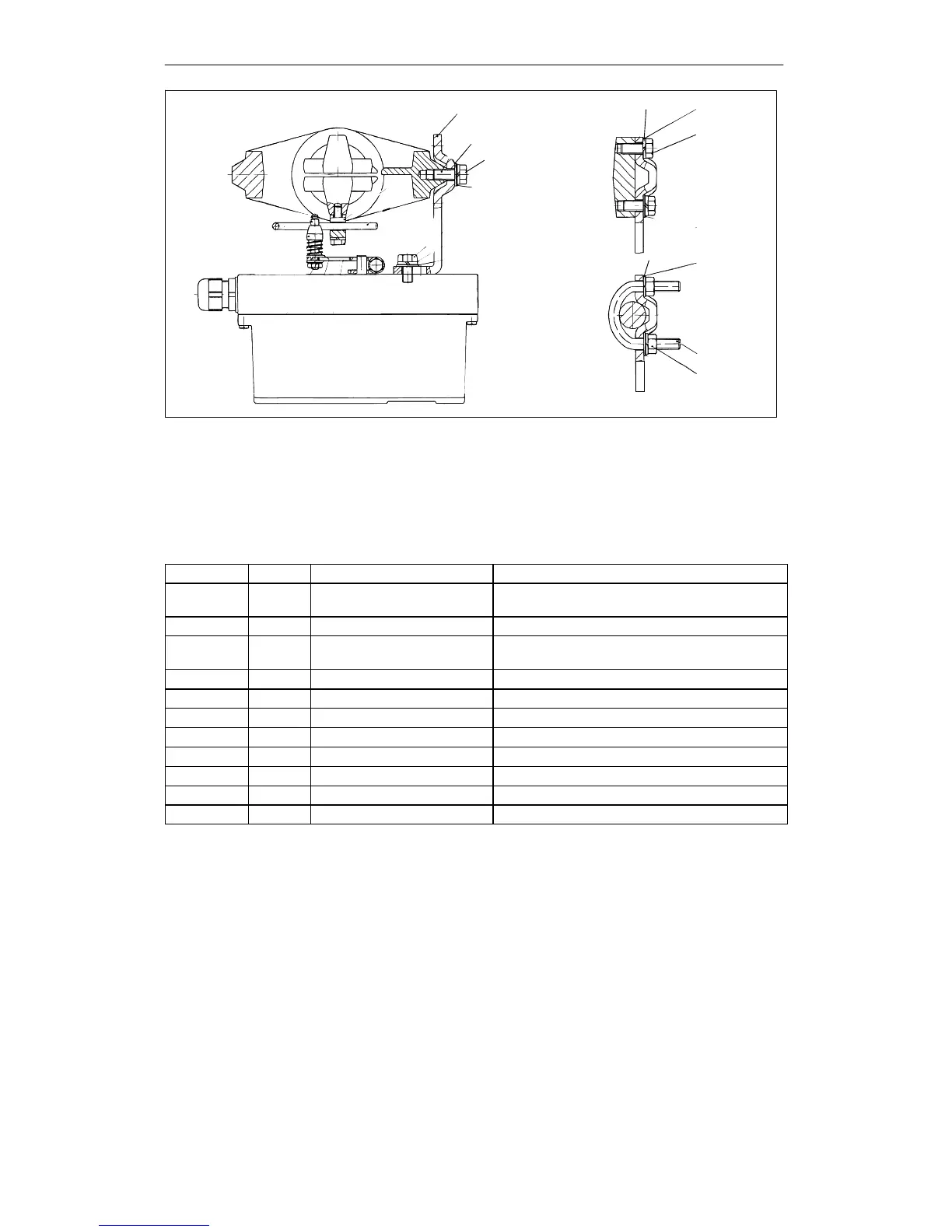
Figure 3-7 Assembly procedure (linear actuator) continued
3.3.5 Mounting kit “part-turn actuator” 6DR4004-8D
The scope of delivery of the mounting kit “part-turn actuator” contains (ser. no. see figures 3-8
and 3-9):
Ser. no. Pieces Designation Note
2 1 Coupling wheel Mounting on position feedback shaft of the
SIPART PS2
3 1 Carrier Mounting on end of actuator shaft
4 1 Multiple plate Indication of actuator position, comprising 4.1
and 4.2
4.1 8 Scales Different divisions
4.2 1 Pointer mark Reference point for scale
14 4 Hexagon head screw DIN 933 -- M6 x 12
15 4 Lock washer S6
16 1 Fillister head screw DIN84--M6x12
17 1 Washer DIN125–6.4
18 1 Hexagon socket head screw Premounted with coupling wheel
19 1 Allen key For item 18
Table 3-2 Scope of delivery of the mounting kit “part-turn actuator”

 Loading...