Functions
2.9 Backup Time Overcurrent Protection
SIPROTEC, 7SD610, Manual
C53000-G1176-C145-6, Release date 02.2011
104
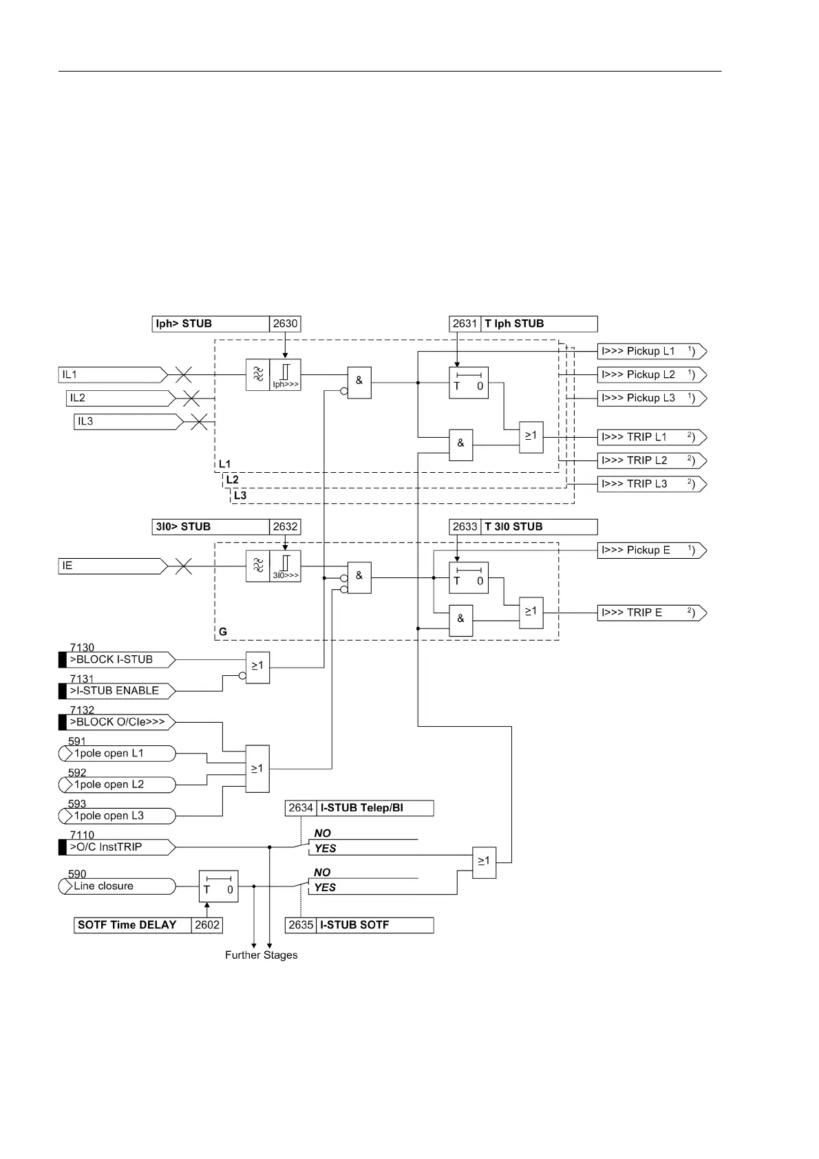
Additional Stage I>>>
An additional overcurrent stage I>>> has an extra enable input (Figure 2-40) It is therefore also suitable e.g.
as an emergency stage if the remaining stages are used as backup stages. The enable input „>I-STUB
ENABLE“ can then be assigned to the output signal „Emer. mode“ (either via binary outputs and inputs or
via the user-definable logic CFC functions). The stage is then automatically active whenever the differential pro-
tection is not effective, e.g. due to a data disturbance.
The I>>> stage can, however, also be used as a standard additional and independent overcurrent stage, since
it works independent of the other stages. In this case, the enable input „>I-STUB ENABLE“ must be activated
permanently (via a binary input or CFC).
Figure 2-40 Logic diagram of the I>>> stage
1
) Output indications associated with the pickup signals are listed in Table 2-3
2
) Output indications associated with the trip signals are listed in Table 2-4

 Loading...


