Functions
2.11 Undervoltage and Overvoltage Protection (optional)
SIPROTEC, 7SD610, Manual
C53000-G1176-C145-6, Release date 02.2011
155
Overvoltage positive sequence system U
1
The device calculates the positive sequence system according to its defining equation
U
1
=
1
/
3
·(U
L1
+ a·U
L2
+ a
2
·U
L3
)
where a = e
j120°
.
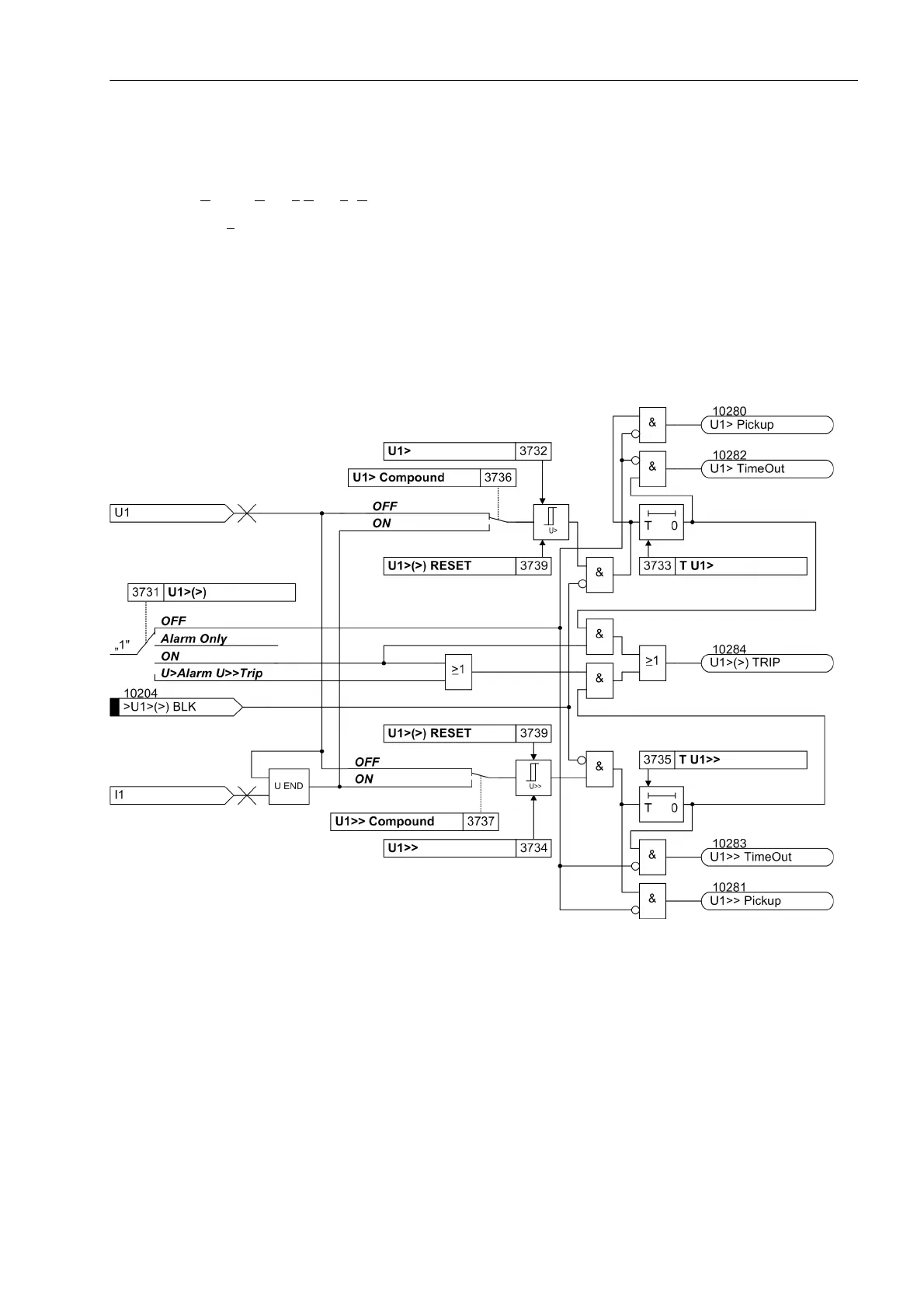
The resulting positive sequence voltage is fed to the two threshold stages U1> (address 3732) and U1>> (ad-
dress 3734) (see Figure 2-57). Combined with the associated time delays T U1> (address 3733) and T U1>>
(address 3735), these stages form a two-stage overvoltage protection based on the positive sequence system.
Here too, the drop-out to pickup ratio can be set.
The overvoltage protection for the positive sequence system can also be blocked via a binary input „>U1>(>)
BLK“.
Figure 2-57 Logic diagram of the overvoltage protection for the positive sequence voltage system

 Loading...


