Functions
2.11 Undervoltage and Overvoltage Protection (optional)
SIPROTEC, 7SD610, Manual
C53000-G1176-C145-6, Release date 02.2011
157
Overvoltage negative sequence system U
2
The device calculates the negative sequence system voltages according to its defining equation:
U
2
=
1
/
3
·(U
L1
+ a
2
·U
L2
+ a·U
L3
)
where a = e
j120°
.
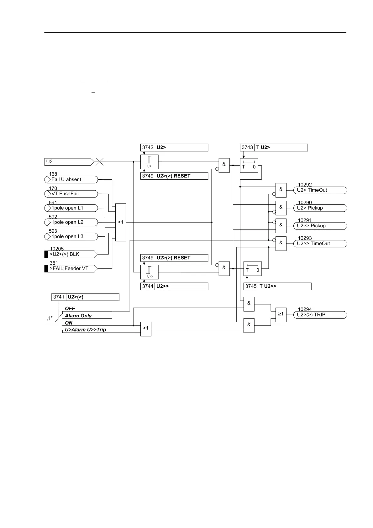
The resulting negative sequence voltage is fed to the two threshold stages U2> (address 3742) and U2>> (ad-
dress 3744). Figure 2-59 shows the logic diagram. Combined with the associated time delays T U2> (address
3743) and T U2>> (address 3745), these stages form a two-stage overvoltage protection for the negative se-
quence system. Here too, the drop-out to pickup ratio can be set.
Figure 2-59 Logic diagram of the overvoltage protection for the negative sequence voltage system U
2
The overvoltage protection for the negative sequence system can also be blocked via a binary input „>U2>(>)
BLK“. The stages of the negative sequence voltage protection are automatically blocked as soon as an asym-
metrical voltage failure was detected („Fuse Failure Monitor“, also see Section 2.15.1, margin heading „Fast
Fuse Failure Monitor (Non-symmetrical Voltages))“ or when tripping of the MCB for voltage transformers has
been signalled via the binary input „>FAIL:Feeder VT“.
During the single-pole dead time, the stages of the negative-sequence overvoltage protection are automatically
blocked since the occurring negative sequence values are only influenced by the asymmetrical power flow, not
by the fault in the system. If the device cooperates with an external automatic reclosure function, or if a single-
pole tripping can be triggered by a different protection system (working in parallel), the overvoltage protection
for the negative sequence system must be blocked via a binary input during single-pole tripping.

 Loading...


