Functions
2.15 Monitoring Functions
SIPROTEC, 7SD610, Manual
C53000-G1176-C145-6, Release date 02.2011
202
After a settable time (5 s-100 s), this malfunction is signalled as „Fail I balance“ (no. 163).
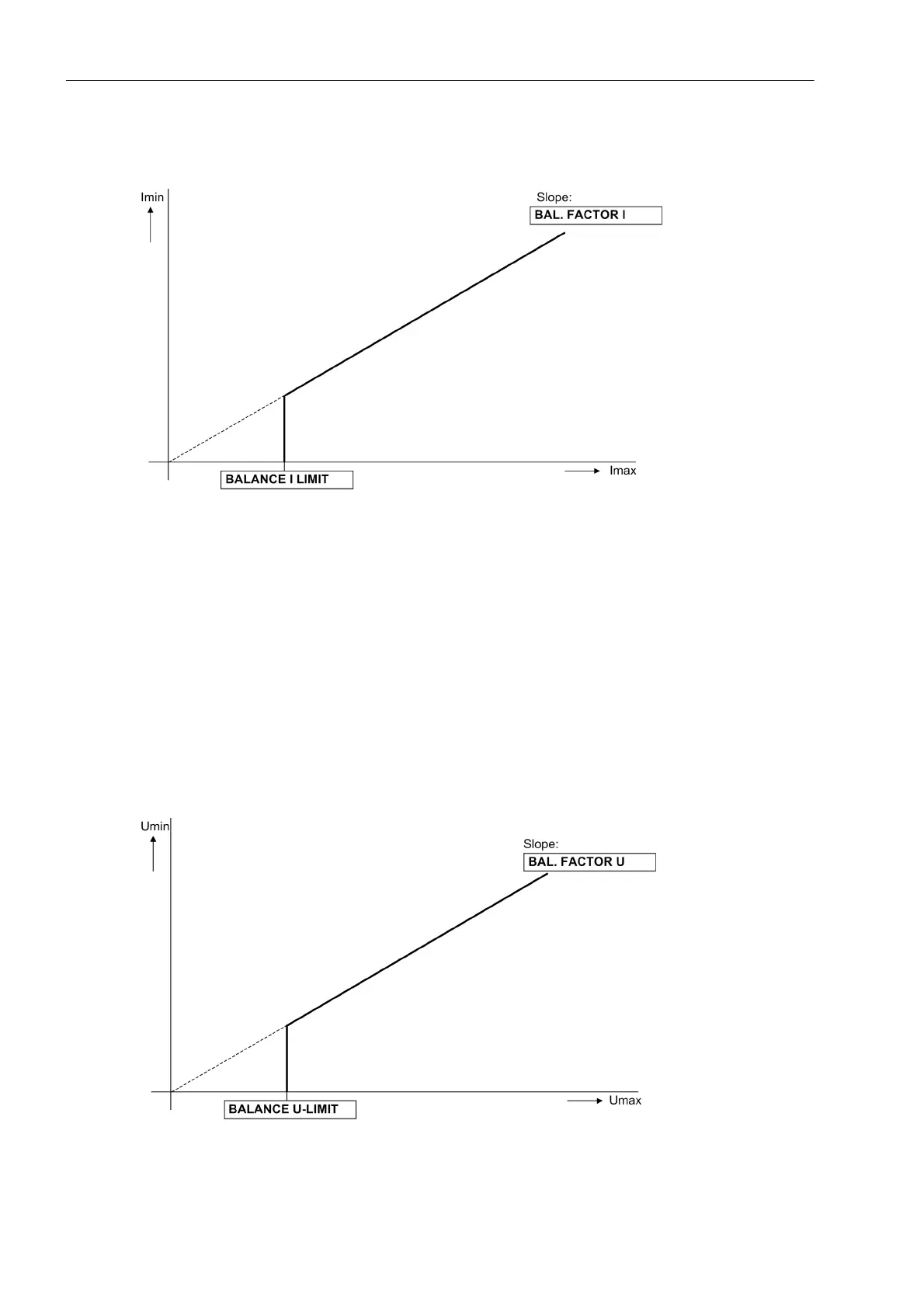
Figure 2-84 Current symmetry monitoring
Voltage Symmetry
During normal system operation the voltages are assumed to be largely symmetrical. The symmetry is moni-
tored in the device by magnitude comparison. The smallest phase voltage is compared to the largest. Asym-
metry is recognized if:
|U
min
| / | U
max
| < BAL. FACTOR U as long as | U
max
| > BALANCE U-LIMIT
Thereby U
max
is the largest of the three phase-to-phase voltages and U
min
the smallest. The symmetry factor
BAL. FACTOR U (address 2903) represents the allowable asymmetry of the voltages while the limit value
BALANCE U-LIMIT (address 2902) is the lower limit of the operating range of this monitoring (see Figure 2-
85). The resetting ratio is about 97 %.
After a settable time, this malfunction is signaled as „Fail U balance“ (no. 167).
Figure 2-85 Voltage symmetry monitoring

 Loading...


