Mounting and Commissioning
3.1 Mounting and Connections
SIPROTEC, 7SD610, Manual
C53000-G1176-C145-6, Release date 02.2011
281
The set nominal current of the current input transformers are checked on the input/output board C-I/O-11. The
jumpers X60 to X64 must all be set to the same rated current, i.e. one jumper (X61 to X64) for each input trans-
former of the phase currents and in addition the common jumper X60.
Jumper X64 is plugged in position „IE“.
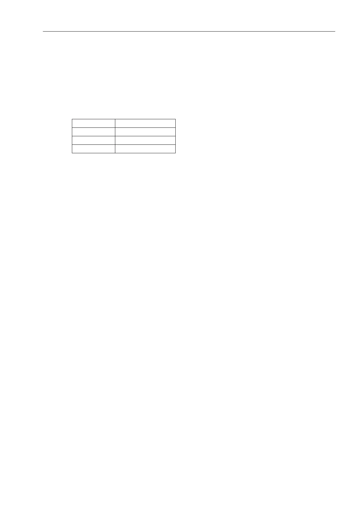
Jumpers X71, X72 and X73 on the input/output board C-I/O-11 are used for setting the bus address and must
not be changed. The following Table lists the jumper presettings.
Table 3-9 Jumper settings of Bus Address of the input/output board C-I/O-11
Slot of input/output board C-I/O-11: No. 2 in Figure 3–33-3.
Jumper Presetting
X71 1-2(H)
X72 1-2 (H)
X73 2-3 (L)

 Loading...


