Mounting and Commissioning
3.1 Mounting and Connections
SIPROTEC, 7SD610, Manual
C53000-G1176-C145-6, Release date 02.2011
280
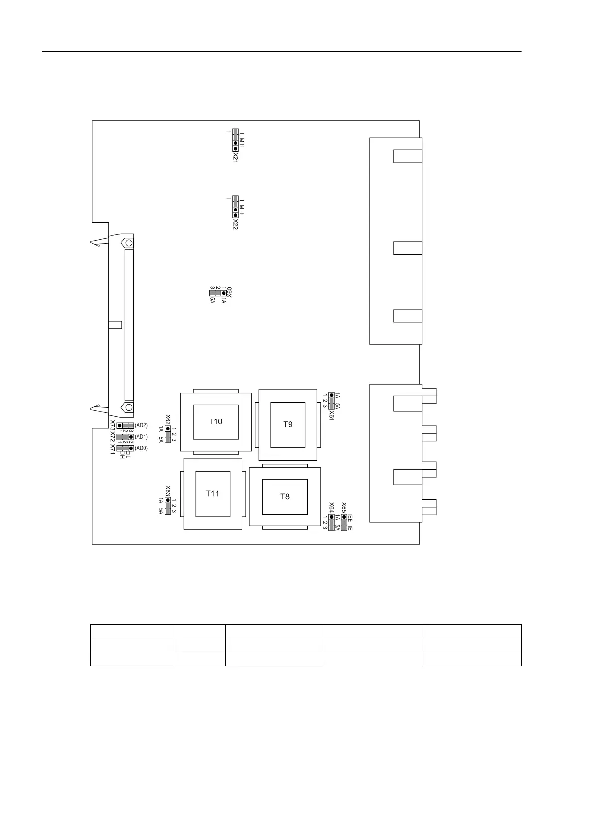
Input/Output Board C-I/O-11
Figure 3-6 C-I/O-11 input/output board with representation of jumper settings required for checking con-
figuration settings
Table 3-8 Jumper settings for Control Voltages of the binary inputs BI6 and BI7 on the input/output board
C-I/O-11
1)
Factory settings for devices with power supply voltages of DC 24 V to 125 V
2)
Factory settings for devices with power supply voltages of DC 110 V to 250 V
3)
Use only with pickup voltages of DC 220 V to 250 V and AC 230 V
Binary input Jumper 17 V Threshold
1)
73 V Threshold
2)
154 V Threshold
3)
BI6 X21 L M H
BI7 X22 L M H

 Loading...


