Mounting and Commissioning
3.1 Mounting and Connections
SIPROTEC, 7SD610, Manual
C53000-G1176-C145-6, Release date 02.2011
279
With interface RS232 jumper X111 is needed to activate CTS which enables the communication with the
modem.
Table 3-6 Jumper setting for CTS (Clear To Send, flow control) on the C-CPU-2 processor board
Jumper setting 2-3: The connection to the modem is usually established with a star coupler or fibre-optic con-
verter. Therefore the modem control signals according to RS232 standard DIN 66020 are not available. Modem
signals are not required since the connection to the SIPROTEC 4 devices is always operated in the half-duplex
mode. Please use the connection cable with order number 7XV5100-4.
Jumper setting 1-2: This setting makes the modem signals available, i. e. for a direct RS232-connection
between the SIPROTEC 4 device and the modem this setting can be selected optionally. We recommend to
use a standard RS232 modem connection cable (converter 9-pin to 25-pin).
Note
For a direct connection to DIGSI with interface RS232 jumper X111 must be plugged in position 2-3.
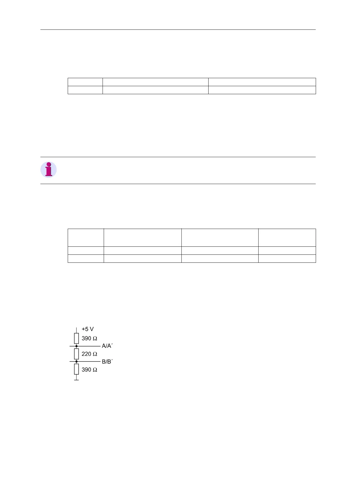
If there are no external terminating resistors in the system, the last devices on a RS485 bus must be configured
via jumpers X103 and X104.
Table 3-7 Jumper settings of the Terminating Resistors of the RS485 interface on the C-CPU-2 proces-
sor board
Note: Both jumpers must always be plugged in the same way!
Jumper X90 has no function. The factory setting is 1-2.
Terminating resistors can also be connected externally (e.g. to the terminal block). In this case, the terminating
resistors located on the RS485 or PROFIBUS interface module or directly on the PCB of the processor board
C-CPU-2 must be de-energized.
Figure 3-5 Termination of the RS485 interface (external)
Jumper /CTS from Interface RS232 /CTS Controlled by /RTS
X111 1-2 2-3
Jumper Terminating Resistor
enabled
Terminating resistor
disabled
Presetting
X103 2-3 1-2 1-2
X104 2-3 1-2 1-2

 Loading...


