Mounting and Commissioning
3.1 Mounting and Connections
SIPROTEC, 7SD610, Manual
C53000-G1176-C145-6, Release date 02.2011
278
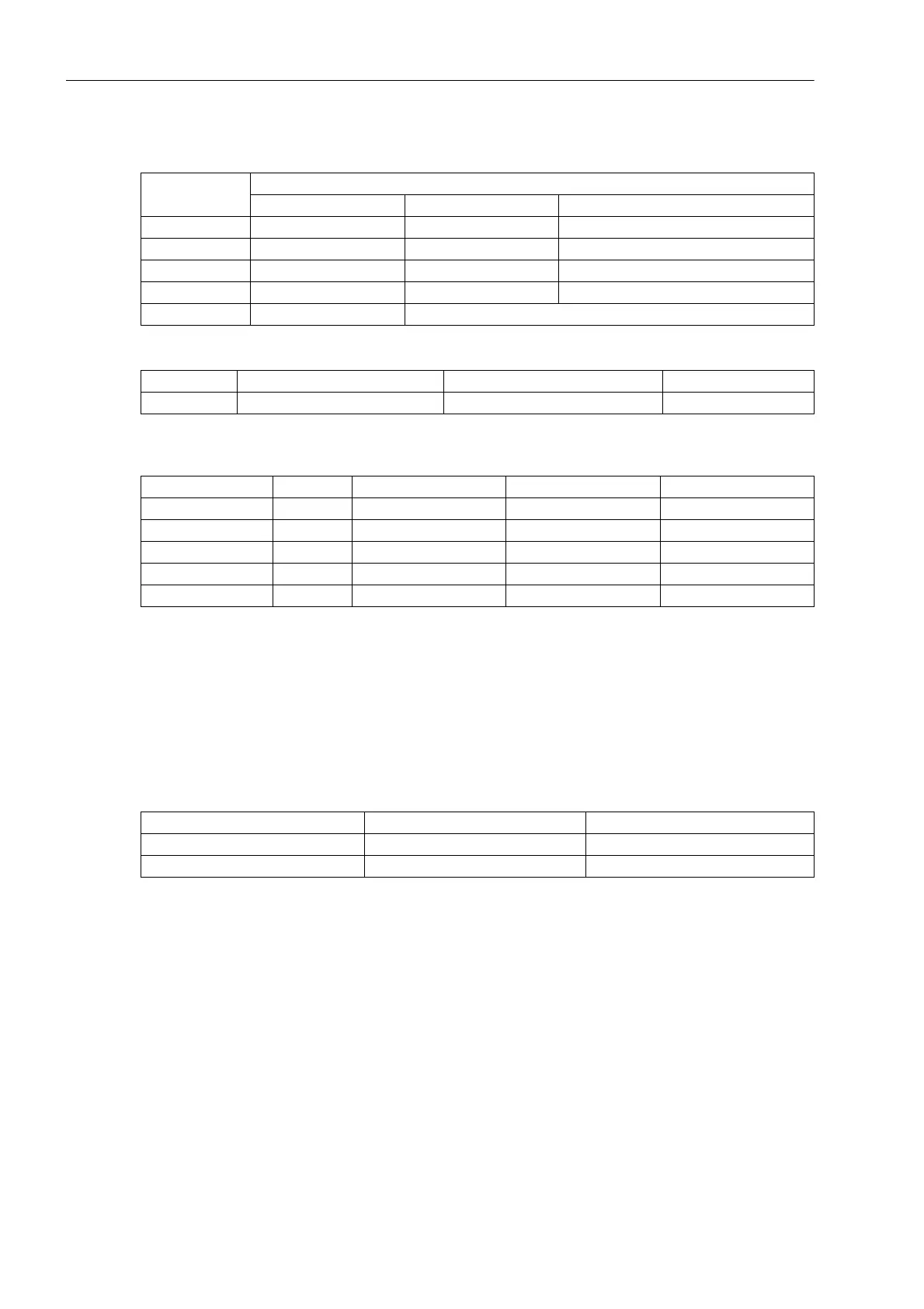
Table 3-2 Jumper setting of the rated voltage of the integrated Power Supply on the C-CPU-2 processor
board
Table 3-3 Jumper setting of the quiescent state of the Life Contact on the processor board C-CPU-2
Table 3-4 Jumper setting of the Control Voltages of the binary inputs BI1 to BI5 on the C-CPU-2
processor board
1)
Factory settings for devices with power supply voltages of DC 24 V to 125 V
2)
Factory settings for devices with power supply voltages of DC 110 V to 250 V and AC 115 V
3)
Use only with control voltages DC 220 V or 250 V and AC 250 V
By repositioning jumpers the interface RS485 can be modified into a RS232 interface and vice versa.
Jumpers X105 to X110 must be set to the same position.
Table 3-5 Jumper settings of the integrated RS232/RS485 Interface on the C-CPU-2 processor board
The jumpers are preset at the factory according to the configuration ordered.
Jumper Nominal voltage
DC 24 V to 48 V DC 60 V to 125 V DC 110 V to 250 V, AC 115 V/230 V
X51 Not used 1-2 2-3
X52 Not used 1-2 and 3-4 2-3
X53 Not used 1-2 2-3
X55 Not used Not used 1-2
Fuse T4H250V T2H250V
Jumper Open in the quiescent state Closed in the quiescent state Presetting
X40 1-2 2-3 2-3
Binary Inputs Jumper 17 V Threshold
1)
73 V Threshold
2)
154 V Threshold
3)
BI1 X21 1-2 2-3 3-4
BI2 X22 1-2 2-3 3-4
BI3 X23 1-2 2-3 3-4
BI4 X24 1-2 2-3 3-4
BI5 X25 1-2 2-3 3-4
Jumper RS232 RS485
X103 and X104 1-2 1-2
X105 to X110 1-2 2-3

 Loading...


