Mounting and Commissioning
3.3 Commissioning
SIPROTEC, 7SD610, Manual
C53000-G1176-C145-6, Release date 02.2011
312
• The current transformer connections are tested at each end of the protected object with current flowing
through the protected object.
• After closing the circuit breakers, none of the measured value monitoring functions in the 7SD610 must re-
spond. If there was a fault indication, however, the Event Log or spontaneous indications can be checked to
investigate the reason for it.
– If current summation errors occur, check the matching factors (see Section 2.1.2 under margin heading
„Connection of the currents“).
– Indications from the symmetry monitoring could occur because there actually are asymmetrical condi-
tions in the primary system. If they are part of normal operation, the corresponding monitoring function is
set less sensitive (see Section 2.15.1 under margin heading „Symmetry Monitoring“).
The currents can be read as primary and secondary values on the display at the front, or called up in the PC
via the operator or service interface, and compared with the actual measured quantities. The phase differ-
ences of the currents are indicated in addition to the absolute values so that the correct phase sequence
and polarity of individual transformers can also be seen.
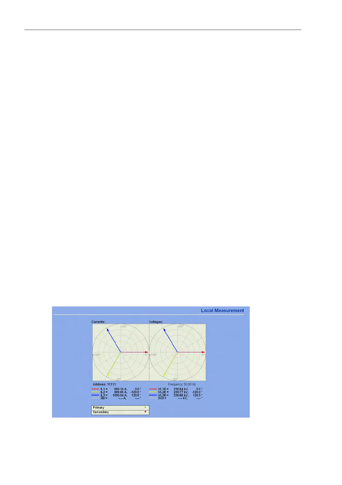
The „WEB-Monitor“ allows convenient readout of all measured values with visualization by means of phasor
diagrams (Figure 3-24).
• The current amplitudes must be approximately the same. All three angles ϕ (I
Lx
–I
Ly
) must be approximately
120°.
– If the measured values are not plausible, the connections must be checked and corrected after switching
off the protected object and short-circuiting the current transformers. If, for example, the phase difference
between two currents is 60° instead of 120°, one of the currents must have a reversed polarity. The same
is the case, if a substantial earth current 3I
0
occurs:
3 I0 ≈ phase current → one or two phase currents are missing;
3 I0 ≈ twice the phase current → one or two phase currents have a reversed polarity.
• The measurements are to be repeated after correcting the connections.
• The above described tests of the measured quantities also have to be performed at the other end of the
tested current path. The current value of the other end can also be read out locally as percentage values as
well as the phase angles.
In the „WEB-Monitor“, the local and remote measured values can be graphically displayed. The following
figures show an example.
Figure 3-24 Local measured values in the WEB-Monitor - Examples of plausible measured values

 Loading...


